NSX supports static routing as well as dynamic routing protocols to provide connectivity to workloads hosted in vSphere environment to the outside word, in case of dynamic routing, neighbor failure detection, or next hop reachability can be determined with keepalives, for example in case of OSPF , it’s the hello and dead intervals and in BGP it’s the keepalive messages, BFD can be used with dynamic routing protocols to support faster failover times.
Static routing can be configured on a T0 gateway, toward external subnets with a next hop of the physical upstream device. To protect the static routes, BFD is highly recommended to detect the failure of the upstream device.
The timers depend on the edge node type, edge VMs support minimum of TX/RX 500 ms and baremetal edges support a minimum of 50 ms.
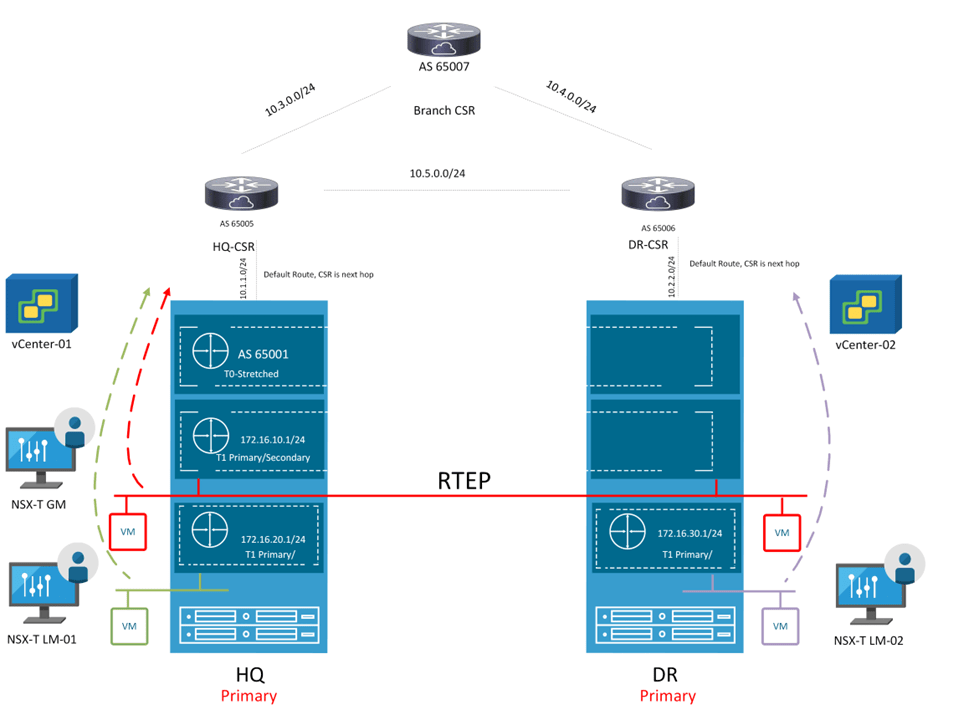
In this blog, we’ll configure T0 with static routing and BFD with some failover scenarios while testing N/S reachability, the below diagram is the architecture we’ll reference in this blog post.
Figure 1 Edge node Design:
Figure 2 T0 logical design:
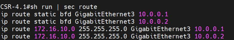
This is a snippet from the configuration of the upstream device:
The interface gigaethernet3 configuration
This BFD configuration matches the BFD configuration used in defining a BFD peer under T0 shown later.
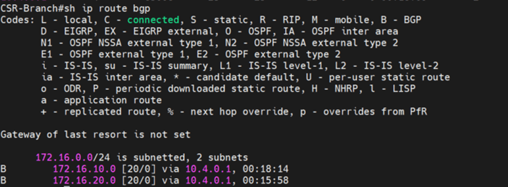
The static routes configured with BFD towards the edge nodes 1 and 2:
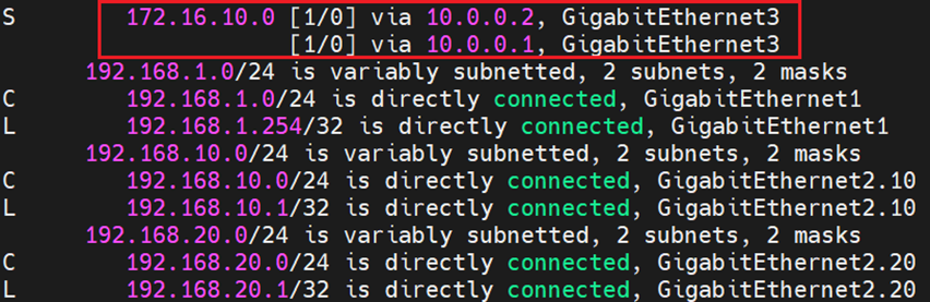
And finally the routing table which shows ECMP configuration of the static route pointing to the overlay segment in NSX:
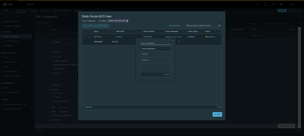
From NSX, the below configuration was made:
The default BFD Profile was used, which has the same timers as the ones configured in Cisco:
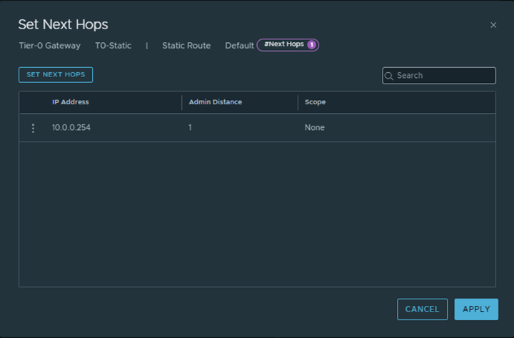
And Finally a default route was configured from T0 gateway pointing towards the Physical upstream device:
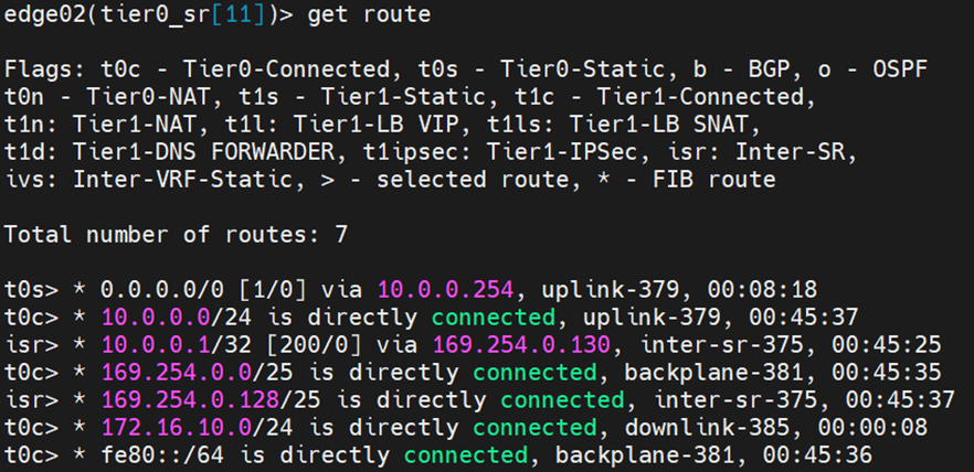
From Edges CLI, let’s validate the routing table of each:
Edge node 1:
Edge Node 2:
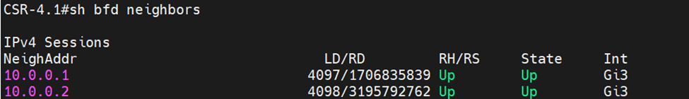
Let’s validate that BFD is up before testing failover scenarios:
From Physical upstream device:
From each edge node:
Edge Node 1:
Edge Node 2:
Testing N/S reachability before failover
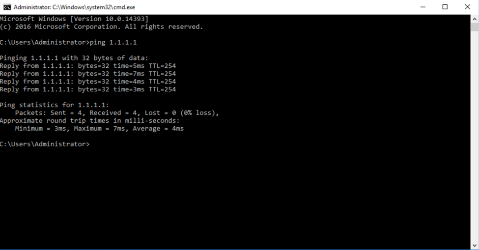
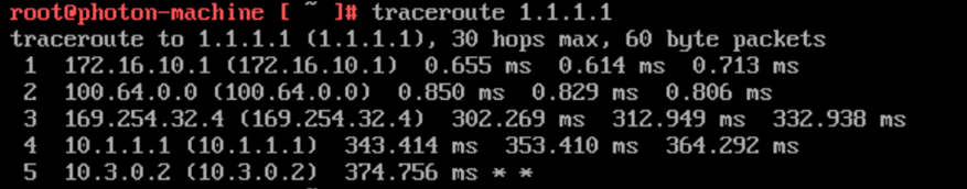
I’ve created a loopback on the physical upstream device with ip 1.1.1.1/32, to test connectivity we pinged from a test VM on the overlay segment in NSX:
To test failover, I’ll change the IP of the uplink interface of Edge node 1 to 10.0.0.3 instead of 10.0.0.2
From the upstream device, the routing table has changed:
Let’s examine the routing table from each edge node:
Edge Node 1:
Edge Node 2:
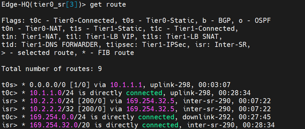
Notice here that edge node 2 learnt the default route from the isr, the reason is explained as per the reference design guide below:
When Inter-SR routing is enabled by the user, an overlay segment is auto plumbed between SRs (similar to the transit segment auto plumbed between DR and SR) and each end gets an IP address assigned in 169.254.0.128/25 subnet by default. An IBGP session is automatically created between Tier-0 SRs and northbound routes (EBGP and static routes) are exchanged on this IBGP session
After correcting the uplink IP of Edge Node 2, you can see the default route in the routing table pointing to the physical device
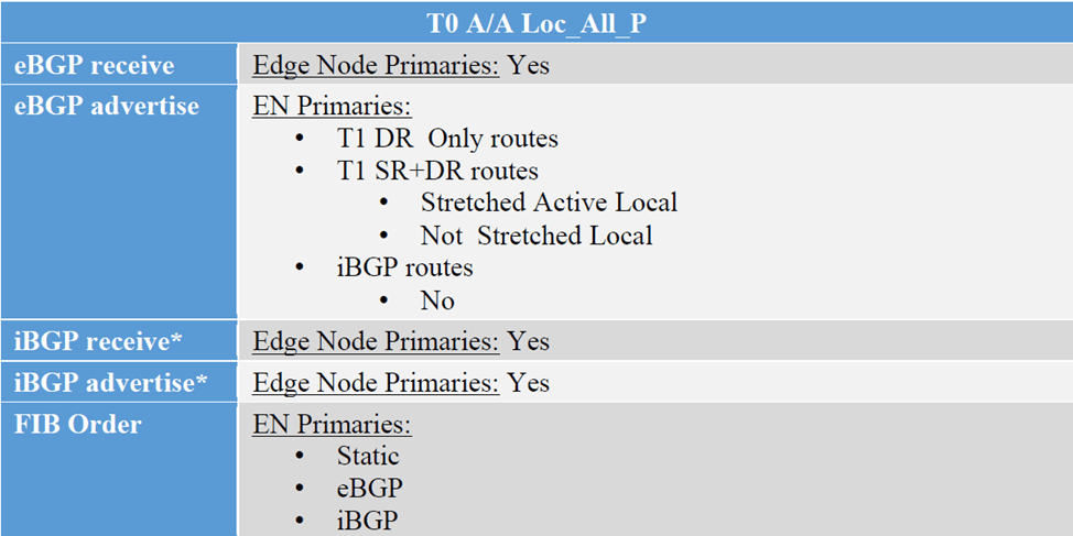
In this final blog for NSX Federation, we’ll discuss the third configuration option for T0 which is “Active/Active Location All Primary” , this option is for T0s without services, VMs egressing from their location, will send the traffic to their local Edge Nodes, supporting local egress. The below is the route exchange between T0 A/A All Primary and the upstream device,
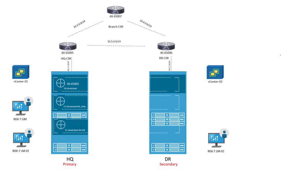
However in this blog, we will go with T1 with custom span and monitor the traffic flows
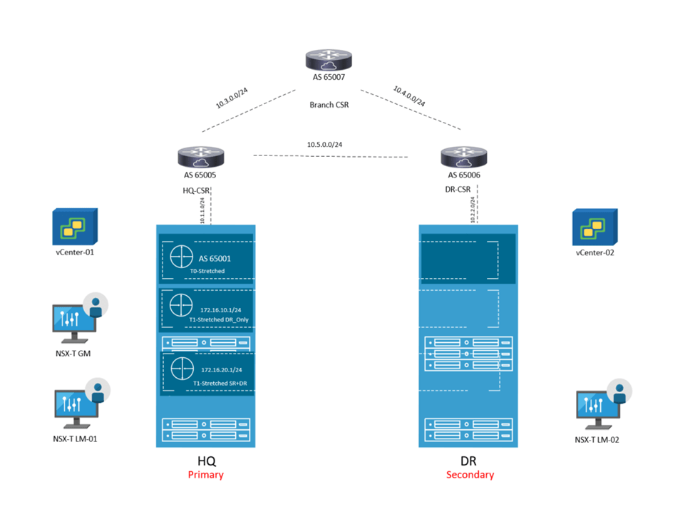
Looking back at the previous topology, the mode of T0 is changed and also added 3 T1s instead, where 2 T1s are location specific having only one primary location and another T1 with custom span, having HQ as primary and DR as secondary
First Change the mode of the T0 to “Mark All locations as Primary”:
Next, let’s create Default route on each location pointing to the corresponding CSR:
Let’s verify from edge nodes:
HQ:
DR:
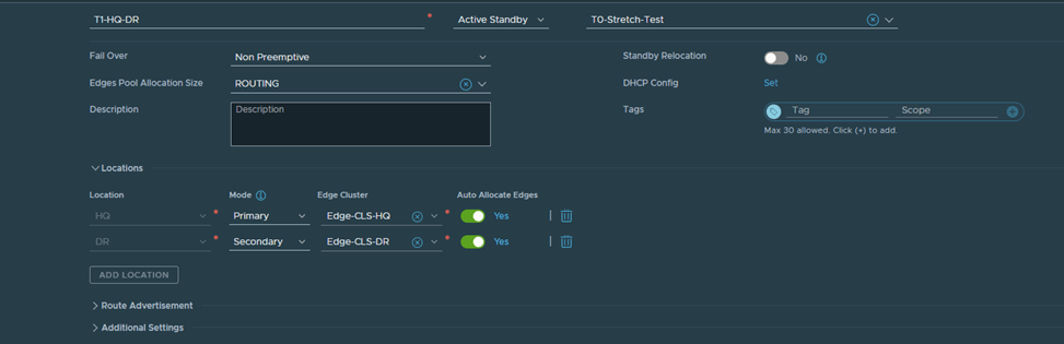
Let’s Now create the three T1s, according to the diagram above,
T1-HQ with HQ only as the primary location:
T1-DR with DR only as the primary location:
Finally Create the last T1 with HQ as Primary and DR as Secondary:
After Creating the segments and connecting them to their respective T1s accordingly:
Let’s verify the span of each T1 created from Edge nodes in HQ and DR:
Edge Node in HQ:
As you can see, T1-HQ and T1-HQ-DR are existing here due to their span which is HQ and DR respectively
Edge Node in DR:
As you can see, T1-DR and T1-HQ-DR are existing here due to their span which is HQ and DR respectively
Let’s verify from the edge nodes the forwarding table of each T1 SR component:
T1 HQ:
You can see that this points to T0 DR So if a VM in HQ is connected to a segment which is connected to T1-HQ communicates South North, the traffic flow will be: T1-HQ DR –>T1-HQ SR–>T0 Stretched DR–>T0 Stretched SR–>Upstream Device
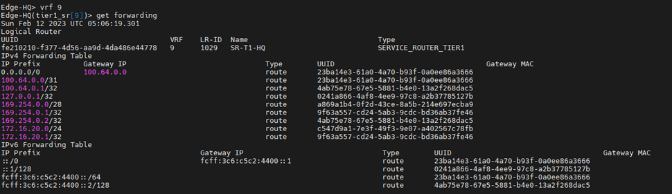
For T1 HQ-DR SR, we will verify the forwarding table from edge node in HQ and edge node in DR: HQ edge node:
So if a VM in HQ is connected to a segment which is connected to T1-HQ-DR communicates South North, the traffic flow will be:
T1-HQ-DR DR –>T1-HQ-DR SR–>T0 Stretched DR–>T0 Stretched SR–>Upstream Device
DR edge node:
Notice here, the default route on the T1-HQ-DR SR component is learned from 169.254.32.2 which is the Intersite Transit Subnet field. This subnet is used for cross-location communication between gateway components
So if a VM in DR is connected to a segment which is connected to T1-HQ-DR communicates South North, the traffic flow will be:
let’s check the forwarding table for Lets check the forwarding table of T1-DR
So if a VM in DR is connected to a segment which is connected to T1-DR communicates South North, the traffic flow will be:
T1-DR DR –>T1-DR SR–> T0 Stretched DR–>T0 Stretched SR–>Upstream Device
Finally, let’s check the routing table of T0 stretched SR component in each site:
HQ:
First 2 routes are advertised from the two T1s, which have span HQ and HQ-DR , last highlighted route is known from iBGP (RTEP) between two sites.
DR:
First two routes are known from iBGP (RTEP) and the last one is known from T1-DR which spans DR only
So quoting from the multi-locations design guide, this is how the traffic flow will be from each site:
Let’s customize this in our topology instead
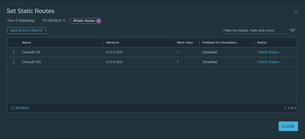
Let’s create the below static routes:
HQ-CSR:
DR-CSR:
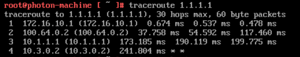
After Redistributing into BGP, let’s do a traceroute from test VMs in each of the 3 segments to a loopback IP in the branch router.
Traceroute from a VM in HQ connected to a segment connected to T1-HQ-DR:
Traceroute from a VM in HQ connected to a segment connected to T1-HQ:
Traceroute from a VM in DR connected to segment connect to T1-DR:
Traceroute from a VM in HQ connected to a segment connected to T1-HQ-DR:
Notice here that the VM in DR site, crossed the intersite link to egress form HQ , this means any VM connected to a segment connected to T1 with custom span, will always egress from the site listed as primary in T1
In this Blog we’ll discuss how changing the T0 mode to Active/Active instead of Active/Standby, have impact on the physical network.
Let’s examine the routing table of site B CSR
Notice now, the edge in the secondary site is advertising the T1 DR segments, unlike when the T0 mode was P/S active/standby
Now let’s check form the edge side,
Now the edge in the secondary site is advertising T1 DR segments
Cross check with the multilocation guide:
Since now secondaries are advertising the connected routes, the branch router might prefer the secondary site routes, bear in mind that in Primary/Secondary, the egress is always from the primary site, so this might end in asymmetric traffic which will get dropped
So first let’s validate/test two things:
1-The egress of a VM in secondary site
2-The routing table of the branch router and how it reaches the VM in secondary site
First, to examine how the VM in a secondary site egresses, let’ check the routing table ( and the internal VRF) of secondary edge and do a traceroute:
From the above, it’s clearly that the secondary edge will prefer the default route learned from the primary edge node (learned from iBGP) due to higher Local Preference.
Let’s check the branch router routing table:
So here it clearly prefers Site B CSR,
In this case the traffic from the VM in a secondary site egresses through primary and ingress will be through secondary,
In this, let’s prefer the edges in primary location, by using AS prepend (making the routes advertised from the secondary site, with higher cost) and check the routing tables again
Create route map with AS prepend:
Apply the route-map to the secondary site neighbor:
Let’s verify the advertised routes from the secondary edge node:
Cross check it with the branch router routing table:
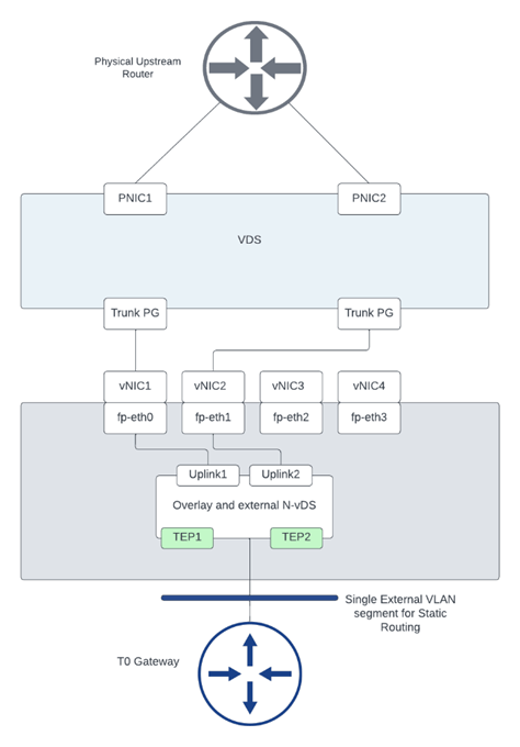
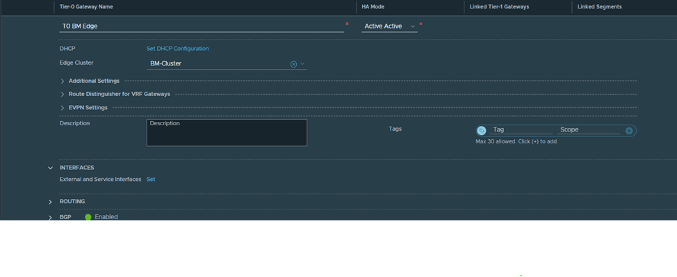
This lab guide is for one of the rare cases in NSX-T which is the BM edge, which is a dedicated physical server that runs a special version of NSX-T Edge software, which provides the following:
Higher bandwidth
Sub-second failure detection between physical and edge node
Dedicated pNICS for Overlay
Dedicated pNICS dedicated for external traffic
A lot more details and different design considerations can be found in the reference design guide:
However, in this document we will focus mainly on the configuration part and specifically on the use case, for
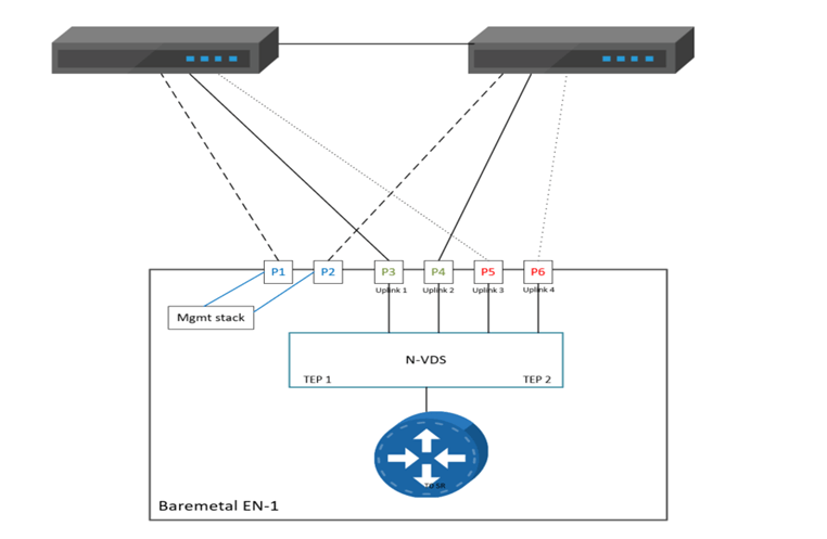
Single N-VDS Bare Metal configuration with six pNICs.Referring to the below diagram, we will use the following:
Management traffic has 2 dedicated pNICs bonded in active stand by
Multi-TEP configured to load balance overlay traffic on Uplink 1 and Uplink 2
Deterministic BGP peering using additional named teaming policies, for VLAN 300 and VLAN 400 respectively, so Uplink 3 will be used to peer with the left TOR and uplink 4 will be used to peer with the right TOR.
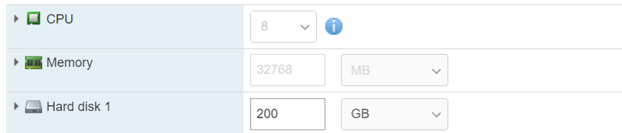
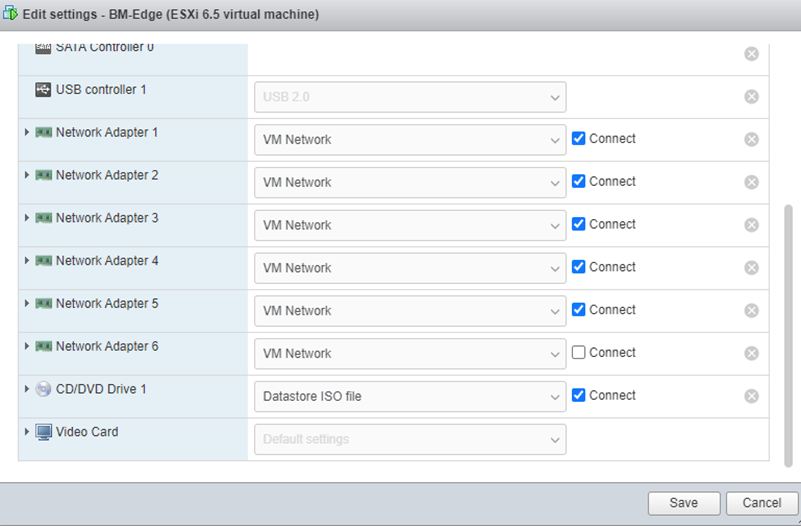
Set the VM resources as the below to meet the minimum BM edge requirements
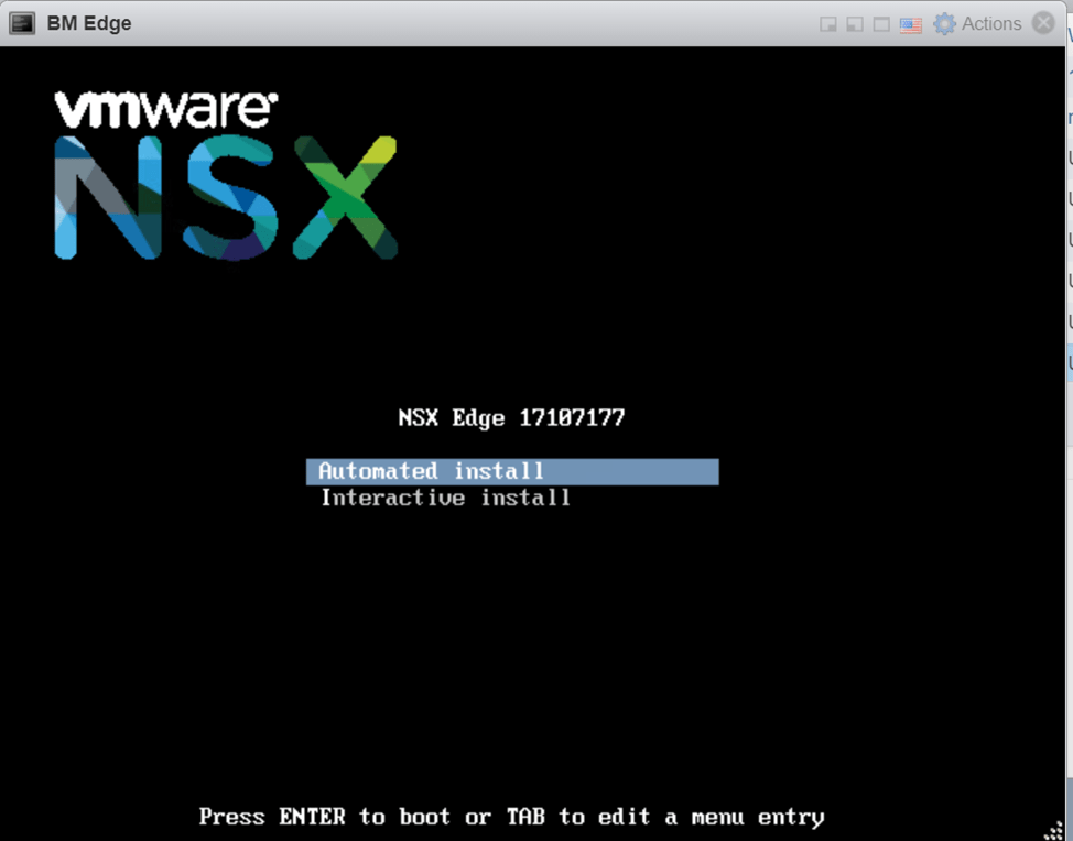
Attach the downloaded ISO file
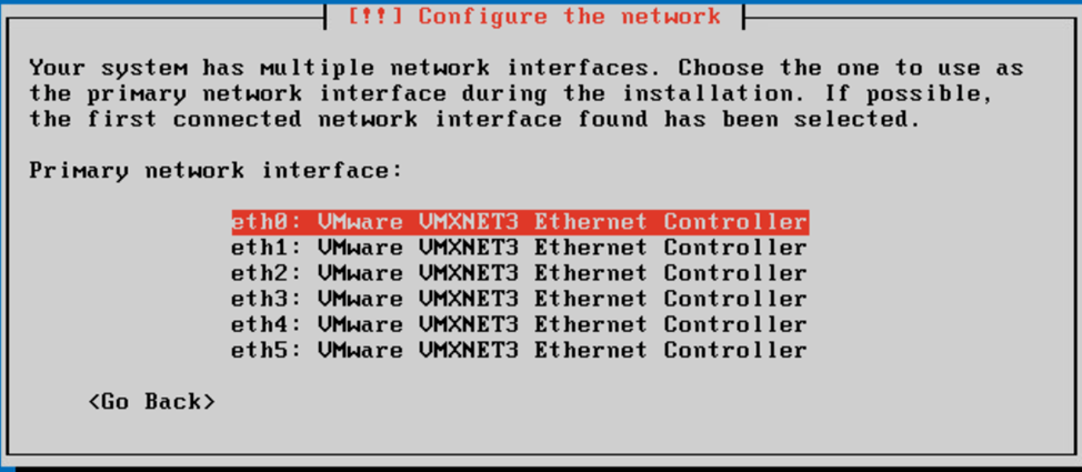
Power on the VM and choose automated install
Choose the first interface (used later for management)
Login using the username admin and the password default, you will then be required to reset the admin password
Since we are going to configure out of band management which supports only active stand by and no VLAN tagging, that’s why the ports connected to the management pNICs should be access ports, below is the command for this configuration from the edge node perspective:
To ease things up, I logged in with root and enabled ssh on the BM Edge, so I can ssh into it instead of console access
The next step is to join the nsx management plane
We need to get the certificate api thumbprint from the nsx manager
After Edge Node registration, we’ll log in to the NSX manager UI and the below is what we see once we navigate to the edge nodes page:
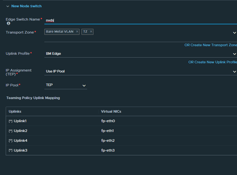
Prior to proceeding with the configuration of the edge node, we will be creating a VLAN TZ with a named teaming policy specified, the reason behind this is if we check the BM edge interfaces again:
We want fp-eth0 and fp-eth1 to carry the overlay traffic and fp-eth2,fp-eth3 to carry the VLAN traffic used for BGP peering, and to accomplish this we will be utilizing the named teaming policy.
So First step is to create a VLAN TZ:
Second is to create an uplink profile similar to the below
We will see later on where we will reference the named teaming policy named1 and named2
Now let’s get back to the edge node and proceed with the configuration:
Upon completion we will notice that the BM edge is configured successfully with the respective IPs
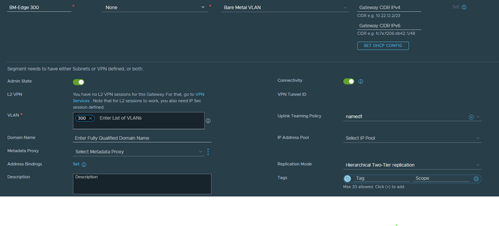
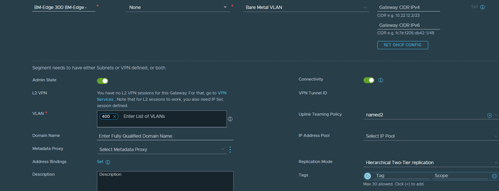
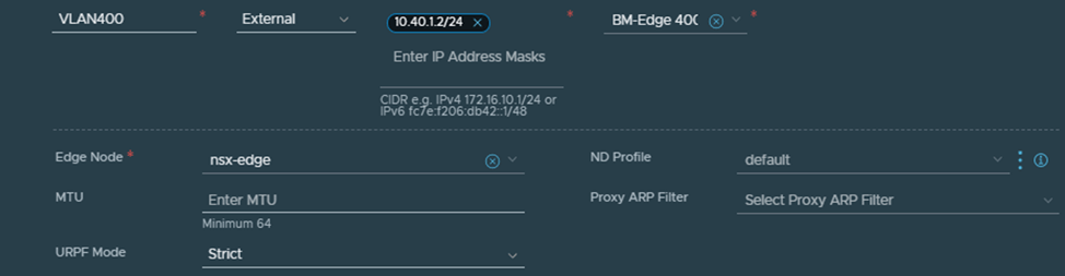
In the next section we will create the Edge Uplink segments and specify the named teaming policy under each VLAN so the BGP traffic is pinned respectively to fp-eth2 (VLAN 300) and fp-eth3 (VLAN 400)
In order to create a T0 on the newly created edge node we need to create the edge uplink segments used for peering and also configure the edge cluster (normally 2 or more nodes, but since this is a lab we will use only one node which we configured earlier)
Let’s create VLAN 300 and VLAN 400 segments, we will start with VLAN 300:
Notice here two things, the VLAN TZ defined is the same one defined in the Edge node configuration, the named teaming policy defined here (named1) is the same as the one defined when we created the TZ and used in the uplink profile
Next we configure the interfaces based on the previously created uplink segments:
The corresponding point to point interfaces are configured on the Cisco for VLAN 300 and 400
For the sake of simplicity the above interfaces are configured on the same router instead of two routers as per the diagram and since BGP configuration is pretty straight forward we will proceed without it but what matters here is that we need to validate that VLAN 300 is pinned to fp-eth2 and VLAN 400 is pinned to fp-eth3 and since the mapping is not exact (for example eth0 and eth1 configured for management is mapped to vmnic1 and vmnic5 of the VM) so to make sure that fp-eth1 is mapped to VLAN 300 we are going to ping from the CSR the point to point interface 10.30.1.2 and disconnect the vmnics (2,3,4,6) one at a time, to prove that the named teaming policy is correct and that it follows the below diagram:
NSX-T federation is of the two multisite solutions (NSX-T multisite is the other one) , it was introduced in 3.0 and recommended in NSX-T 3.1 onwards, it basically consists of one Global manager offering networking and security services to multiple locations, in each location there is one NSX-T local manager cluster.
In this blog, we will focus on one of the routing scenarios discussed in the NSX-T multilocation guide (referenced at the end), which is T0 A/S Loc P/S, but first we will go step by step how to setup federation between two sites, configure RTEPs, stretching segments and setup routing.
The below is the architecture which is used in this lab:
This set up consists of :
2 NSX-T Local Managers ( 1 at each site) version 4.0.1 1 Global Manager version 4.0.1 ( Not using Standby in this lab) 1 Edge node at each site 2 vCenters version 7.0.1 4 nested ESXi Hosts version 7.0.1 A couple of photon VMs for testing E/W , N/S traffic 3 CSRs ( 1 for each site and 1 branch router to demonstrate traffic flow)
The IP addressing is like the below:
Site-1:
Host TEP: 192.168.70.0/24 Edge TEP: 192.168.80.0/24 RTEP: 192.168.110.0 GW of the above resides on HQ CSR
Below are the steps to configure federation, Global T0 in A/S location P/S
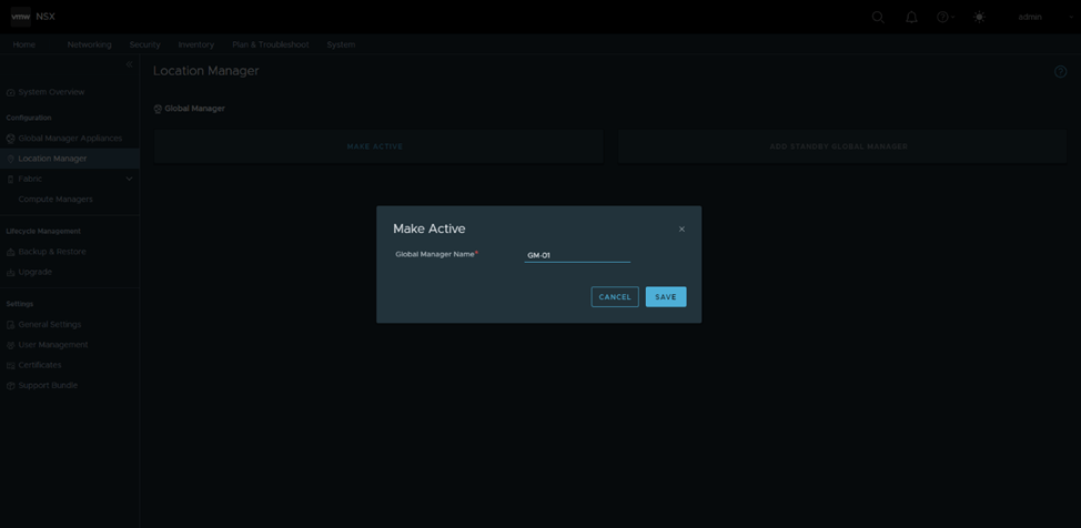
Configure GM in Site-1 as active:
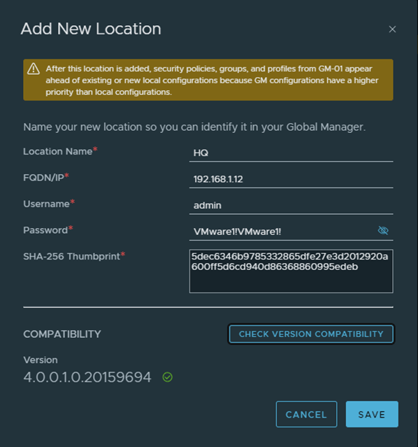
Add HQ as the first location , in order to do that, I got only the manager thumbprint as per the below, in a production environment, you should get the cluster api thumbprint using get certificate cluster thumbprint instead
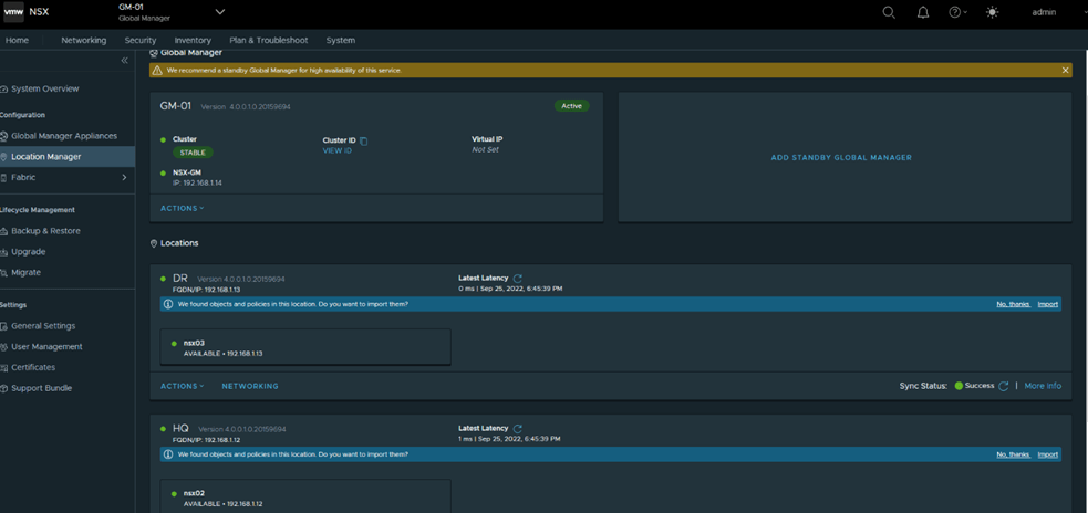
Similarly add DR as the second location and the final status after adding both locations
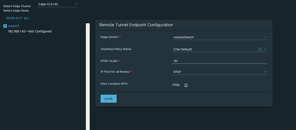
Next is to configure RTEPs, in HQ
Note: The HQ and DR CSRs are routing the RTEP subnets between both sites in this setup
I’ll follow the same steps in DR:
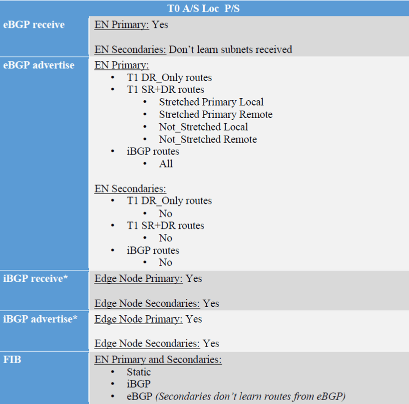
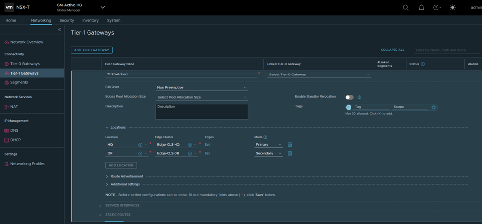
Next, I’ll configure a stretched T0 as per the eBGP details in the diagram (reattaching)
Here you notice HQ is the primary location, DR is the secondary one and the HA mode is Active/Standby BGP neighbors are now up
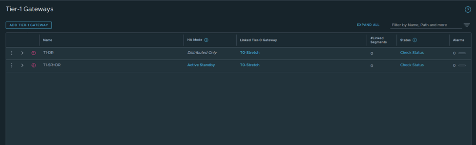
I’ll get back to T0 in detail in a bit, but for now I’ll configure 2 T1s (1 T1 DR only and 1 T1 SR+DR),
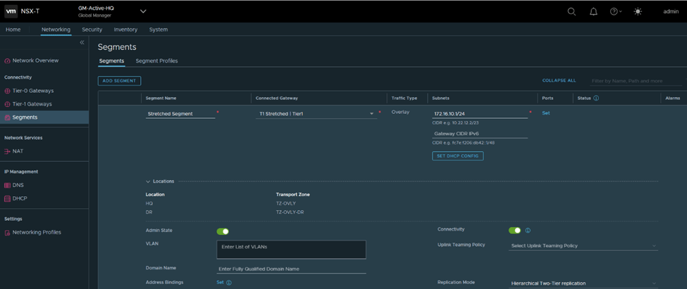
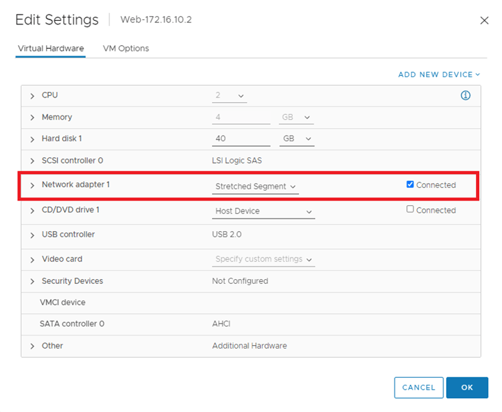
Connect a segment to each and test connectivity
Verify from Edge nodes
Segment 172.16.10.1 will be connected to T1-DR
Segment 172.16.20.2 will be connected to T1-SR+DR
I’ve configured the CSRs to only advertise a default route only to the Stretched T0,
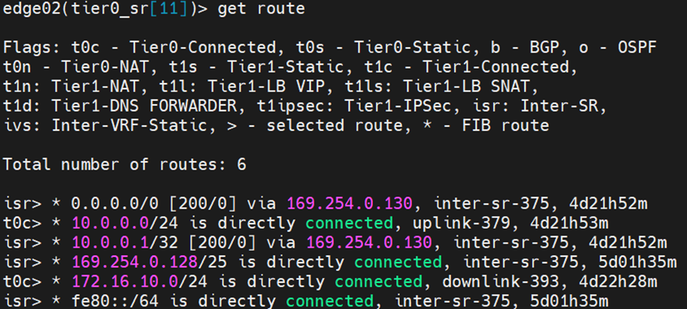
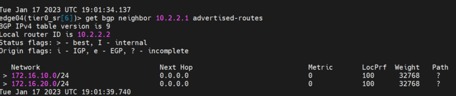
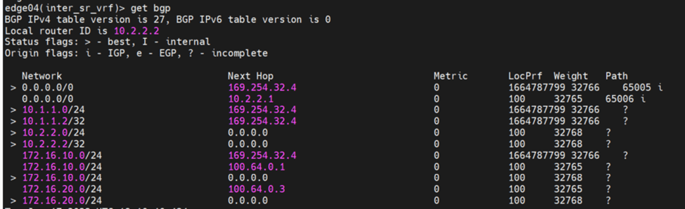
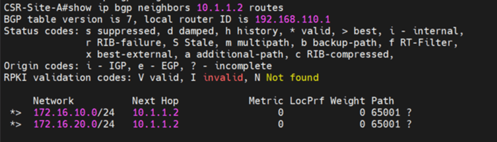
Let’s analyze the primary site edge node routing table
Route 1 : default route received from CSR Route 2: this is the interface connected to T0 for BGP peering Route 3:this is received from isr(iBGP, from the secondary site notice the admin distance) Route 4:same to route 3 Route 5+6:the intertier T0 connected interfaces ( interfaces to which T0 DR connects to T1-DR and T1-DR+SR) Route 7:this is the intra-tier subnet which is between T0 DR and T0 SR Route 8: new subnet created in federation for intersite communication (iBGP) Route 9 + Route 10: T1 connected segments
Let’s check the edge node bgp table
Let’s check from the CSR side in HQ
Let’s cross check this with the reference from the multilocation guide
Primary edge node is :
Receiving default route from CSR –> eBGP receive Advertising the T1-DR, T1-DR+SR –>eBGP advertise Receiving iBGP (with lower local preference)–>iBGP receive Advertising iBGP(directly connected subnets as well as BGP interfaces)–> iBGP advertise
Now let’s check the secondary edge routing table and advertised routes to CSR:
Notice that we are not receiving any eBGP routes, even though default route is advertised from CSR in DRSo secondaries don’t advertise nor receive eBGP routesLast test here to prove that egressing traffic and ingressing traffic goes through Primary T0,
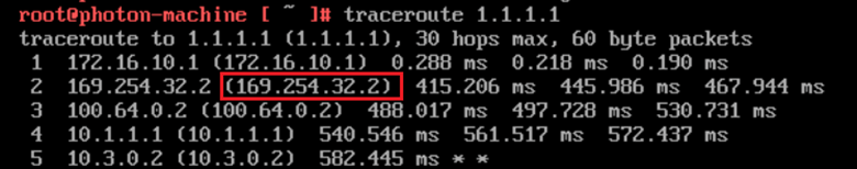
1-We are going to advertise a loopback of 1.1.1.1 from the branch router 2-Do a trace from a VM in the secondary site to the loopback and vice versa 3-Analyze the inbound and outbound traffic
From the branch router it goes the primary edge node
From the VM to the loopback of 1.1.1.1
This again shows that the egress and ingress traffic is from the Primary site/ HQ.
The below steps are an illustration of bridging a federated segment to another VLAN/VXLAN segment, this scenario might be needed in case there is a requirement to maintain layer 2 connectivity between a segment created from the global manager to a normal VLAN segment/portgroup, a VLAN created on the physical devices or even a vxlan logical switch created on NSX-V, bridging a federated segment is done from the local manager, using the manager mode instead of the policy mode, we will start with the below steps:
1-Create Global Tier 1 for stretching one segment:
2- Create a global segment from the global manager, the segment would be stretched between the two sites HQ and DR:
3-Connect a VM to the stretched segment:
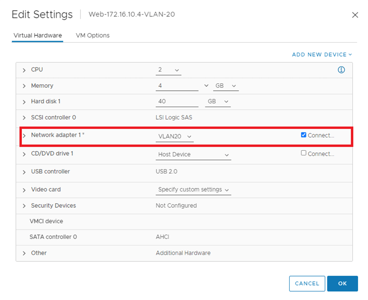
4-Connect another a VM to a VLAN portgroup, VLAN 20 in our example:5-Configure Edge Bridge profile from local NSX-T manager using the manager mode:
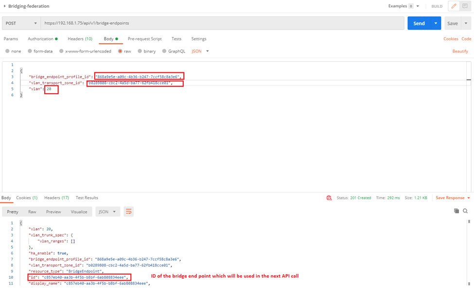
6-Run the below API call to tie the VLAN TZ to the Edge bridge profile created:
We can get the first two highlighted parameters from UI (bridge profile ID and VLAN TZ ID) and the third one is the VLAN ID of the VLAN which will be bridged to the stretched segment, the last one is the bridge end point which we use in a new API call it to create a port on the bridge
7-Run the following API Call to create the port on the bridge, I specified the ID of the stretched segment as well as the id of the bridge endpoint (the output from the previous API call):
8-From the NSX-T manager, manager mode navigate to the logical switch –> Bridge Profiles, you will find the edge bridge profile is mapped to the stretched segment:
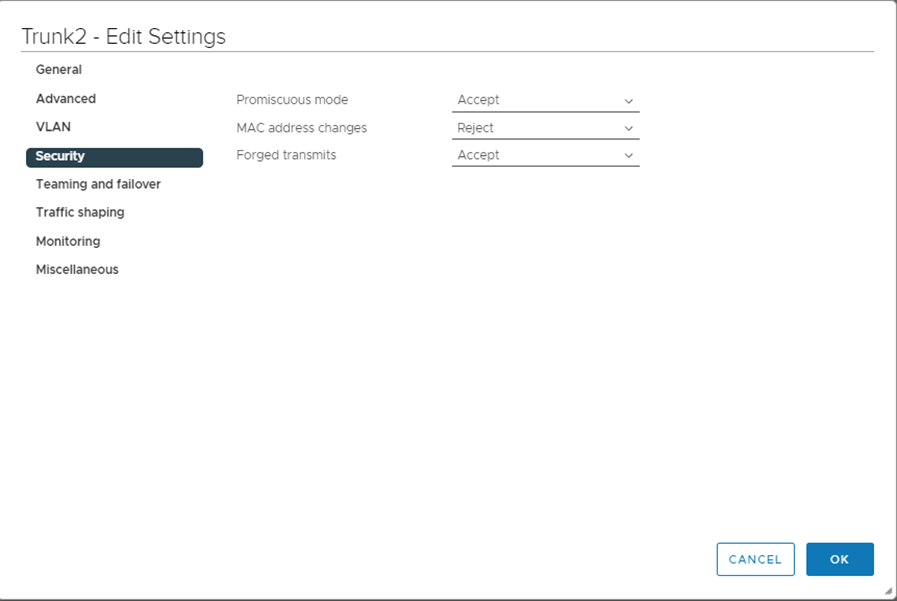
9-Enable Promiscuous mode and forged transmits on the trunk port that connects the edges used in the bridge profile ( to allow traffic to be sourced from different MAC without VDS blocking them)
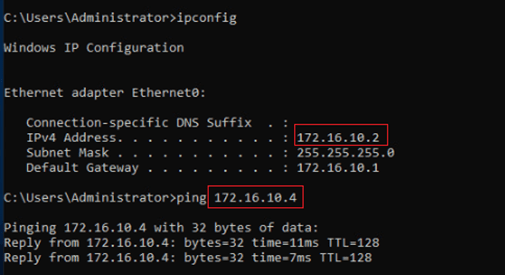
10-Test Pinging from the VM on the stretched segment to the VLAN on portgroup VLAN20,
I’d like to share with you this document, which is based on best effort approach for bridging between NSX-V to NSX-T which can be used as one of the migration approaches .As you know since NSX-V will be deprecated by January 2022, as a result we might be seeing a lot of customers migrating their current environments to NSX-T.
There are different methodologies for that, for example, in parallel upgrade, in place upgrade and so on. For the in parallel upgrade we can create cross connectivity between 2 NSX domains using bridging. Here we have two types of bridging, independent bridging and NSX-T only bridging.
Our focus in this document would be the 2nd type (NSX-T only bridging), which is deploying an NSX-T Bridge on NSX-V prepared hosts, which will be taking advantage of the decapsulation of VXLAN frames happening on the NSX-V hosts and encapsulating these into GENEVE.
We would make use of that, in case of migrating the workloads from NSX-V to NSX-T without affecting internal or external network connectivity; in the means of having the default gateway for a subnet as the DLR interface while the VMs of this subnet might be in the process of migrating between NSX-V to NSX-T, for instance we might have 100 VMs for a web subnet, 50 of them might be existing on NSX-V environment while the rest migrated to NSX-T, both will be using the DLR interface to communicate externally as well as the communication between VMs won’t be interrupted (since we are bridging here between Overlay and VXLAN), this situation is temporary till all VMs migrate to NSX-T environment then we can change the default gateway for a segment to be the T1 interface.
The below diagram is a high-level architecture of the process during the migration between NSX-V and NSX-T, we will cover in the premigration and post migration setup later in detail.
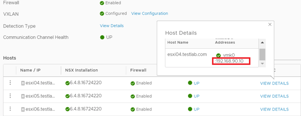
NSX-V: For the 3 hosts prepared for NSX-V, I used the IP Pool 192.168.90.0/24 subnet for host VTEPS as per the below:
NSX-T:
For the 3 hosts prepared for NSX-T, I used the IP pool 192.168.50.0/24 for the hosts TEPs and the IP pool 192.168.60.0/24 for the Edge TEPs (since edges are deployed on Prepared hosts):
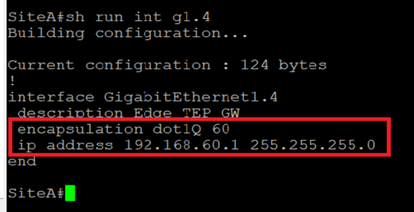
To enable TEP communication between NSX-T hosts and Edges the below is configured on the Cisco CSR:
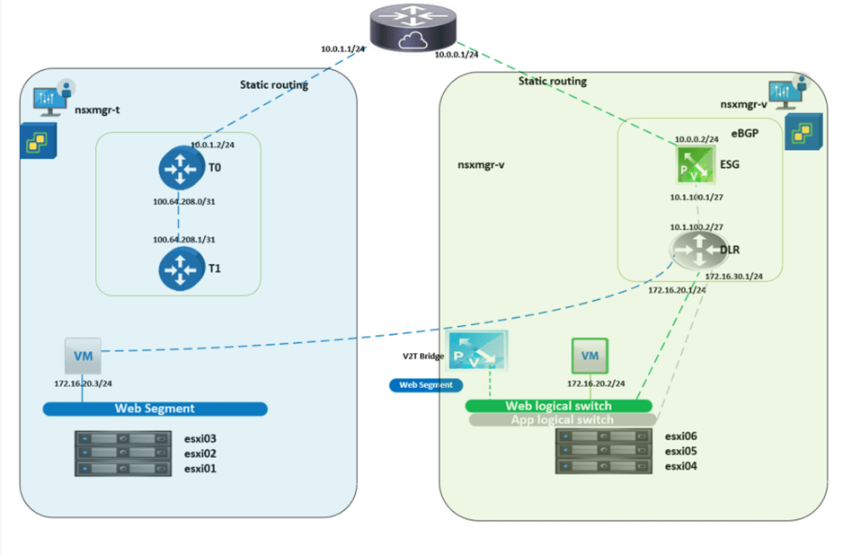
In NSX-V environment I’ve created a 2 logical switches (App and Web), all the migration steps and bridging will be concerned with the Web subnet, the purpose of the App logical switch is to verify that a Web VM migrated to NSX-T can communicate with an App VM via bridging, the Web and App subnets are 172.16.20.0/24 and 172.16.30.0/24 respectively.
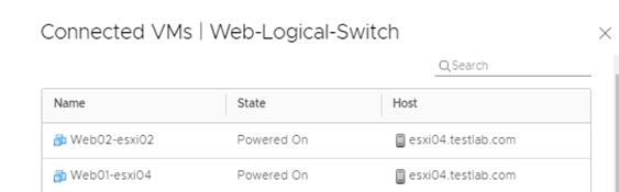
On the Web logical switch, there are 2 VMs (web01 and web02), this is the setup pre migration to NSX-T environment.
Both Logical switches have their default gateways on the DLR installed as per the below:
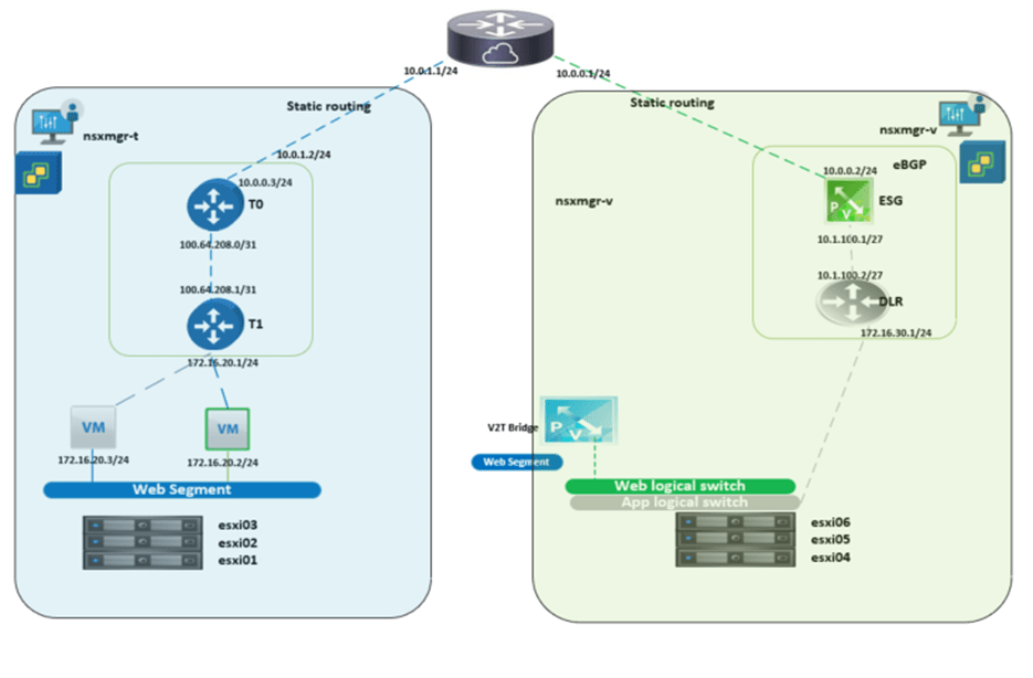
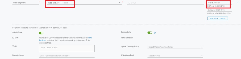
NSX-T: I created an overlay segment called Web, this is the segment where the migrated VMs from Web-logical switch will connect, bear in mind that during the migration, this segment is not connected to a Tier-1 gateway since all the egress traffic goes through the DLR interface if NSX-V.
The logical routing configured here comprises of several parts, between DLR and ESG there is EBGP configured with a default route sent from ESG.
Between ESG and Cisco CSR (L3 device) static routing is configured.
DLR configuration
DLR Routing Table
ESG Configuration
ESG Routing Table
Cisco CSR Routing configuration
NSX-T:
In this setup we have Tier 1 router which is still not connected to the web segment during the migration (it will be connected after the Default Gateway migration from NSX-V to NSX-T) A default route is configured between Tier 0 in NSX-T with the next hop the interface of the CSR. After migrating the Web VMs and their Default Gateway (connecting Web Segment to T1 and setting T1 interface to 172.16.20.1/24), we can then add on the CSR a more specific route “ ip route 172.16.20.0 255.255.255.0 10.0.1.2”, the reason behind this is for the CSR to be able to reach web VMs through Tier 0 and still reach App VMs ( not migrated to NSX-t) through ESG.
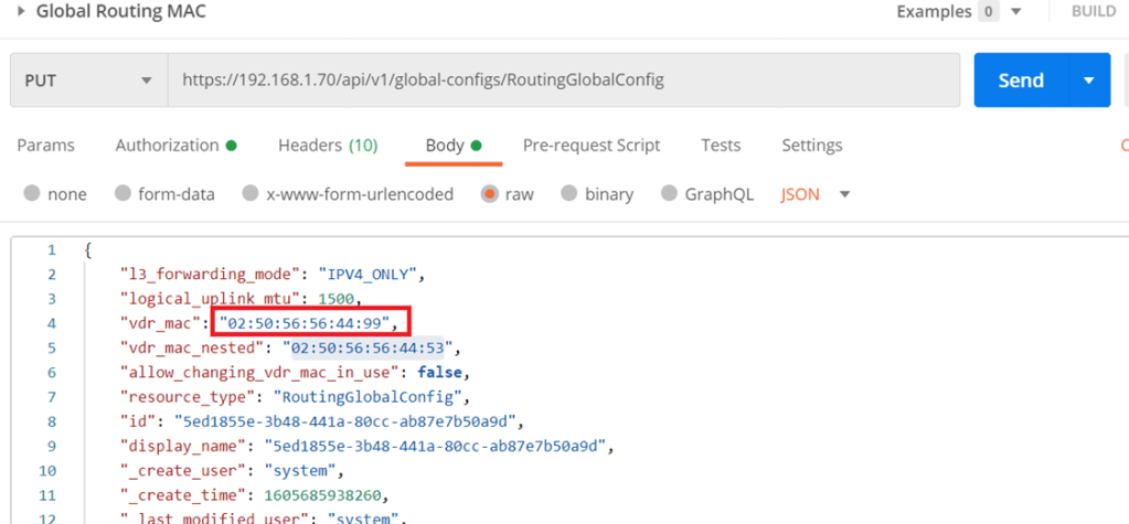
An important thing to note here before setting up any component in NSX-T, is that there was an abnormal behavior reported during the bridging scenario which was as follows, as you know all logical router interfaces have the MAC address “02:50:56:56:44:52”, which sometimes can cause a conflict between both environments (even though in NSX-T the Web segment is not connected to T1) yet this issue was reported on NSX-T 2.5. So, to avoid this we have 2 ways to change the MAC address of the router interfaces.
Either: Run the below to create an overlay transport zone with parameter “nested_nsx”: true which basically changes the MAC address of the router interfaces from “02:50:56:56:44:52” “02:50:56:56:44:53”
Or
Starting NSX-T 3.0.2 you can change the MAC address of the logical interface through an API call (in case none of the transport nodes are created).
The difference here is that I set the MAC address to “02:50:56:56:44:99” which will take effect for any of the created T1 router interfaces
Moving forward, the concept of Edge bridge set up here is to be deployed on NSX-V cluster, which would give the edge bridge the visibility to logical switches configured in the NSX-V environment.
Normally in NSX-T when you deploy an edge VM, it’s uplinks are either connect to VLAN backed segment or DVS VLAN port groups, in this setup we are going to map the edge uplinks to DVS VLAN portgroups and NSX-V logical switche(s).
First of all, in the below edge configuration I’m bridging only one segment, which is the Web segment, however you can bridge another segment if required( App segment) by configuring only 1 uplink for the Overlay instead of 2, then add a 3rd NVDS in which its uplink is connected to the App logical switch (created in NSX-V)
The Bridge-Trunk, is a trunk port group configured on the NSX-V VDS
The Bridge TZ, is a VLAN TZ configured for bridging
In The bridge NVDS, the fp-eth2 is mapped to the web logical switch configured in NSX-V
Which needs to be configured for promiscuous mode and forged transmits
The below screenshot is from the DVS configuration for clarity:
In the above I configured the edge bridge under the Web segment configured in NSX-T and you noticed VLAN 0 (NULL VLAN)
To verify the above setup is working correctly I did a cross vCenter VMotion for one web VM which was connected to the web logical switch to connect to the web segment configured in NSX-T environment.
We will do a couple of ping tests from web02 (172.16.20.3):
ping 172.16.20.2 (web01)
ping 172.16.20.1(DLR interface)
ping 172.16.30.3(App 01)
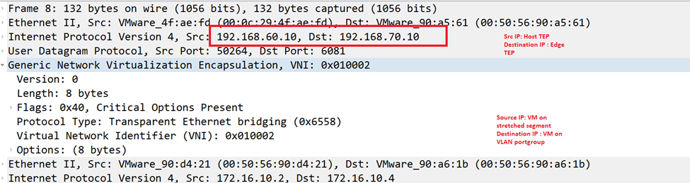
So to deep dive in this part, when the web02 initiates a ping to 172.16.20.2(web-01 on NSX-V) for the first time, it will do an arp request which will be flooded depending on the logical switch replication mode (default is hierarchical but since all TEPS are in the same subnet so the BUM replication will be similar to head replication) so the host where web02 is deployed on will replicate the traffic and sends a copy to each TEP for that particular VNI (web segment), remember that the edge bridge is a transport node at the end and since it’s a member of the overlay transport zone where the web segment is deployed, it will receive the arp request decapsulates GENEVE and examines the request and since the edge bridge is deployed on an esxi host prepared for NSX-V then it will follow the logical switch replication for BUM traffic, the default is unicast, so the host will encapsulate the arp request using VXLAN to the rest of the hosts, finally the bridge MAC-address table will have web-01 MAC:
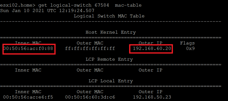
Edge Bridge MAC Address table
ESXi02 which hosts web02 MAC Address table
Notice here that the Outer IP address is the Edge bridge IP, so for future communication with Web01,
The ESXi02 host will encapsulate the traffic via GENEVE and the destination TEP will be the 192.168.60.20 which is the bridge TEP IP, the bridge then will decapsulate the GENEVE header and the ESXi host hosting the edge bridge will encapsulate the traffic via VLXLAN.
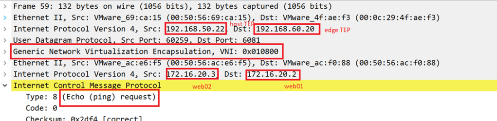
Let’s validate the above with packet captures( we will examine the ones having the destination IP 172.16.20.3 in detail, 172.16.20.1 and 172.16.30.3 should be similar)
Source IP: 172.16.20.3 (web02) on NSX-T segment Destination IP:172.16.20.2 (web01) on NSX-V logical segment
GENEVE Between ESXi02 (which hosts web02) and Edge Bridge
VXLAN between Edge Bridge and ESXi04(which hosts web01):
VXLAN between ESXi04 and ESXi hosting the Edge Bridge
The final step is to migrate the gateway for the web segment to be the Tier 1 interface in NSX-T instead of the DLR interface in NSX-V
Let’s verify a couple of things:
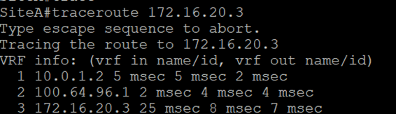
Traceroute from CSR to web02(hosted on NSX-T segment)
Notice here the traffic from CSR to the web02 VM traverses the ESG and DLR routers like the below:
And the goal after the GW migration is to have the below final setup:
To achieve this final setup, we will configure the below:
-Disconnect DLR interface
-Connect Web Segment to Tier 1
-Add more specific route to the CSR for the web subnet (this is needed when there are still subnets communicating with web segment and still not migrated to NSX-T)
Let’s run the traceroute again from the CSR
Now we notice the difference in trace before and after the GW migration.
The above completes the gateway migration simulation on a home lab, bear in mind that high availability was not taken into consideration, which should be noted in real life scenarios.
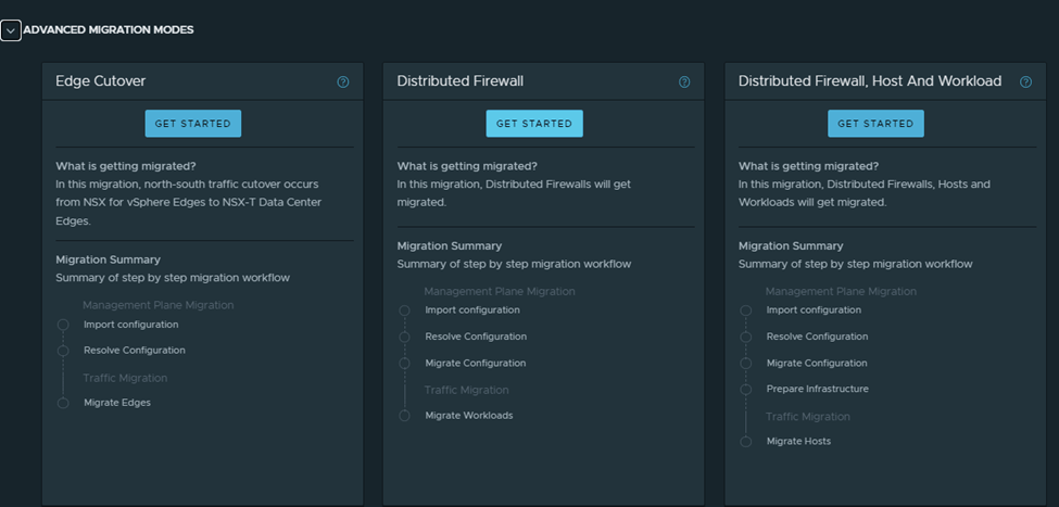
In this mode, the migration coordinator migrates only DFW from NSX Data Center for vSphere to NSX-T Data Center.
The below configurations are migrated:
User-defined Distributed Firewall (DFW) rules
Grouping Objects
IP sets
MAC Sets
Security Groups
Services and Service Groups
Security Tags
Security Policies created using Service Composer (only DFW rule configurations are migrated)
Guest Introspection service configuration and Network Introspection rule configurations in the Service Composer are not migrated.
Important Notes and pre-requisites:
When we use the MC to migrate DFW configuration, the DFW-only migration mode must be run once, after the DFW configuration is migrated to NSX-T, we shouldn’t update the DFW configuration in NSX-V and run the MC again; running DFW-only migration mode is not recommended.
Migration with UI is available starting 3.1.1
L2 bridging should be in place
No user defined rules should exist in NSX-T
No unpublished changes in service composer or DFW in V
Export version of DFW must be set to 1000 on NSX-V hosts
All hosts in NSX-managed cluster (T and V), must be connected to the same version of VDS and each host within the cluster should be a member of a single version of VDS ( needs further explanation)
The FW state is maintained regardless of whether the VMs are migrating in a single vCenter or across vCenters, also dynamic membership is maintained after the MC migrates the Tags to the workload VMs
Objects created during the migration shouldn’t be updated or deleted before the migration finishes.
You can’t migrate VMs again from NSX-T to NSX-V , roll back of migrated VMs is not supported
The workaround is to add the VMs in the NSX-T FW exclusion list then migrate the workload VMs back to NSX-V
DFW exclusion list is not migrated, you need to re-create them on NSX-T after migration
Enter credentials for vCenter and NSX-V (in this case same vCenter is used)
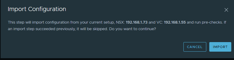
Start with importing the configuration:
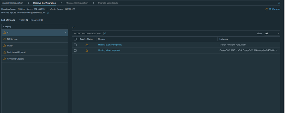
After the successful import, we navigate to the page of resolve configuration which looks like the below:
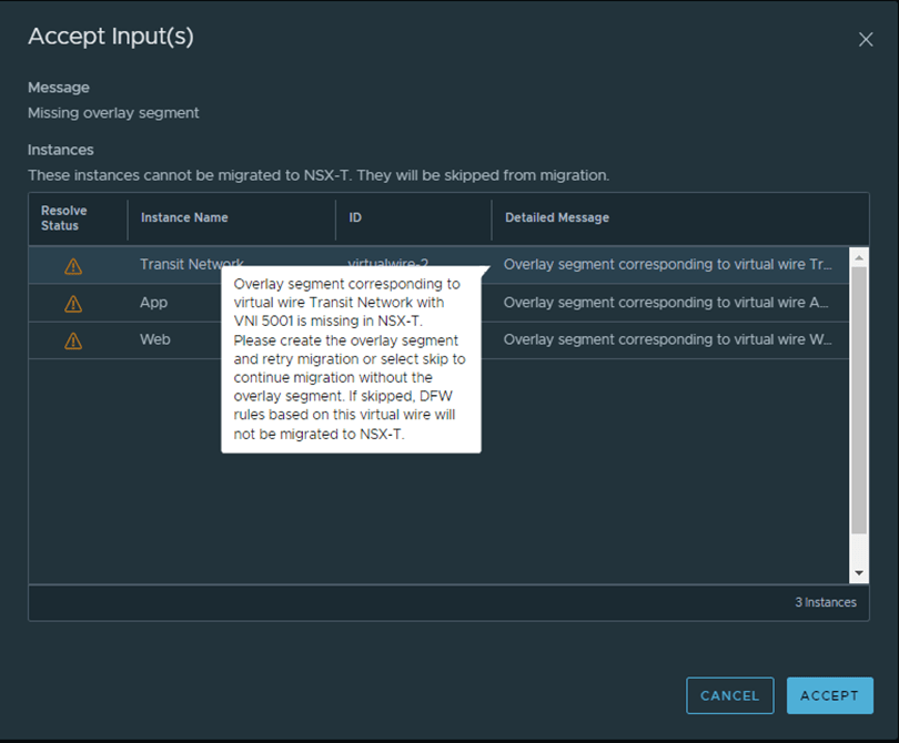
As per the below, I need to create the missing segments in NSX-T with the same VNI:
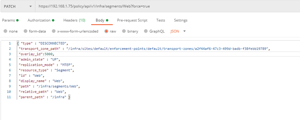
From Postman create the segment with the VNI ID equals the one in NSX-V:
Notice here I’ve some different settings than the example listed in the MC guide, since I don’t want to connect this segment to a T1 yet.
And another one for the App segment:
Now let’s rollback the configuration and retry again:
After importing again, notice that the error for web and app corresponding segments have disappeared:
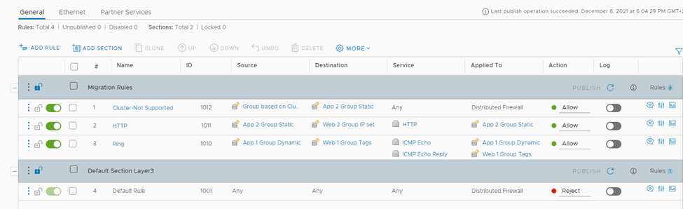
Another warning shows for the rule containing a group based on cluster:
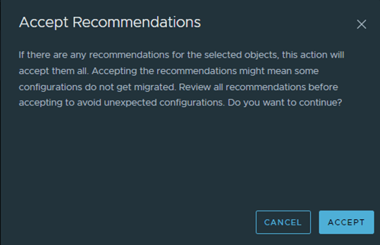
Now let’s accept all the recommendations and start the migration:
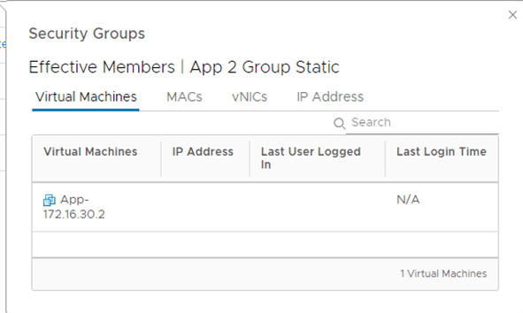
After the migration imported successfully, notice one group is created like the below:
A parent group is created and has two subgroups, when of the is based on IP sets in order not to break the communication between VMs in T and VMs in V
Important notes:
As of NSX-T 3.1.1, the migration coordinator does not modify the NSX-V environment. It is assumed that NSX-V dynamic membership is maintained as long as the VM is in the same vCenter. If you plan to move the VM to another vCenter and maintain security, you must manually create IPsets in NSX-V reflecting the dynamic mappings before moving the VM
During the Migrate Configuration step, Security Tags from NSX-v are not migrated to NSX-T. Therefore, the Security Tag-based migrated dynamic Groups in NSX-T are empty. The reason is that in NSX-v, a Security Tag is an object, whereas in NSX-T, a tag is an attribute of a VM. The tags are applied to the workload VMs only after you migrate the workloads to NSX-T
If the migrated NSX-T Groups have static memberships, these Groups also are empty after this step is finished. The reason is that the static members are not available in NSX-T Groups until the workload VMs are migrated
During vMotion from NSX-v to NSX-T, the workload VMs are always protected because the migration coordinator translates the existing NSX-v DFW rules and security groups into temporary IP-based rules and groups. If your DFW rules consist of VM static memberships and Security Tags, these settings are applied in NSX-T only when the vmgroup API endpoint with post_migrate action is run after vMotion of workload VMs
How the FW rules look like in NSX-T after the migration:
Two ways to migrated workload VMs after you migrate DFW configuration:
If “Applied to” is not used, ie set to DFW
Migrate Workload VMs (Simple Case)
If “Applied to” is used, ie not set to DFW
Use a script to Migrate the VMs (Complex case)
Let’s go with the second use case, since we have applied to field not set to DFW in NSX-V,
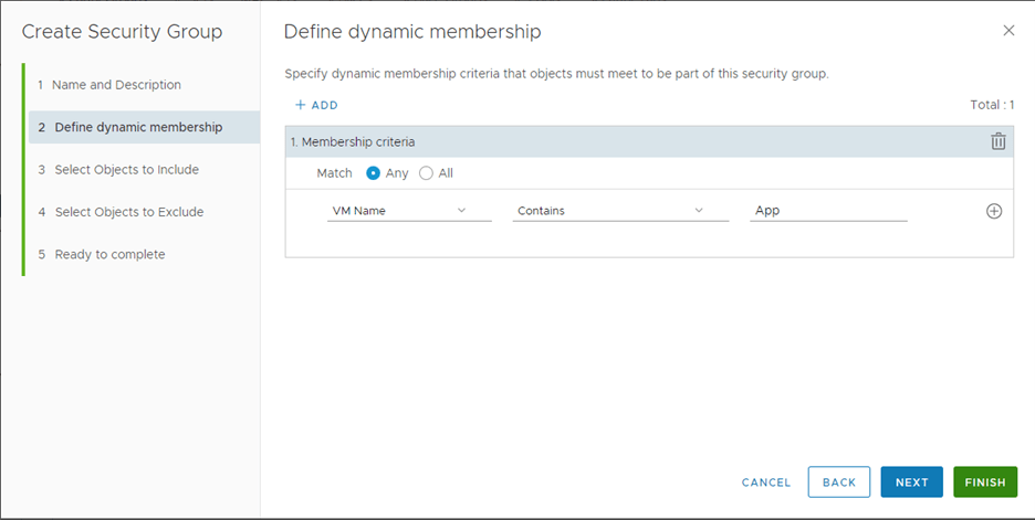
In order to do that we need to create VM Groups for Workload Migration since
the DFW rules in our NSX-v environment use Security Groups with dynamic memberships based on Security Tags or use static memberships. When only IP-based DFW rules are used in NSX-v environment, VM Groups are not required before migrating the workload VMs to NSX-T.
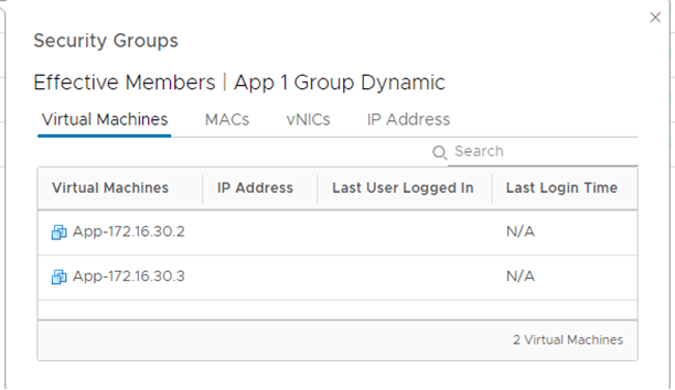
The purpose of this group is to create a VIF for every VM that will be migrated over to NSX-T
We need to get the UUID for every VM to be migrated in order to added to the VM group, we can get this using the MOB or with vSphere APIs, below is how to get from the mob file:
These are the 4 UUIDS, which will be used in the VM group:
5010c3d6-db26-6226-a3e8-76b231156720
50102bb4-615a-6476-2da2-34ec63f71a80
50106272-5cf6-ec3f-de0c-fdea3e38767b
5010d6f5-eb38-bf12-62e2-cf903ddd1929
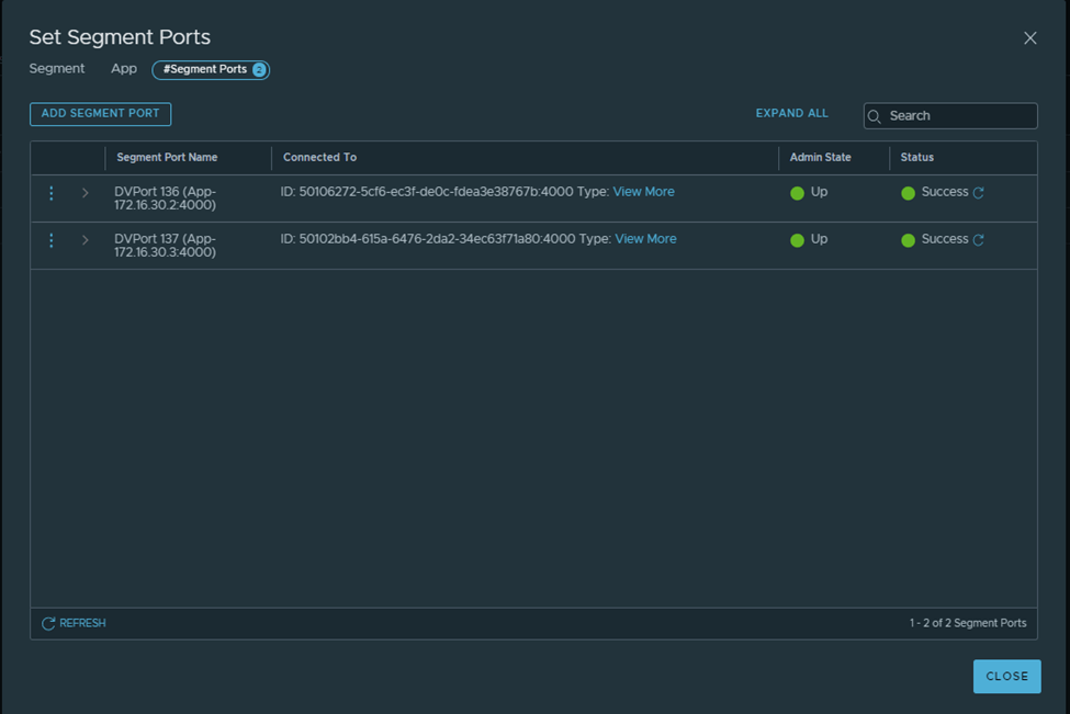
We can add them all at once using the below API call:
Notice the segment ports /VIFs get created under each NSX-T segment:
After Migrating one VM and running the below API call:
You can now see that one group based on static membership has now the VM assigned to it correctly: