In the previous blog, we successfully imported a vSphere enviroment into VCF9 via VCF Operations. In this blog we are going to upgrade the imported workload domain to the recent VCF version 9.0.1
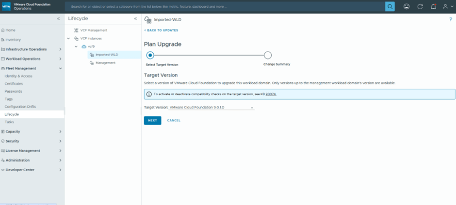
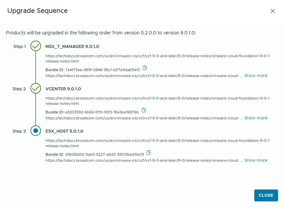
First is to plan the upgrade
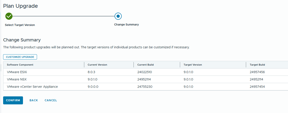
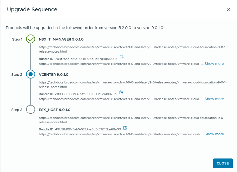
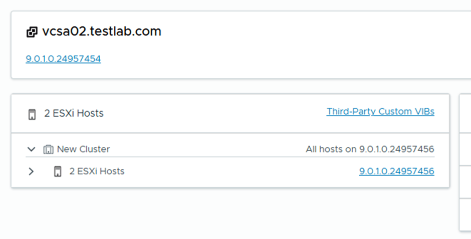
We are going basically to upgrade vCenter and ESX only , since NSX was already deployed during Workload import with the recent version
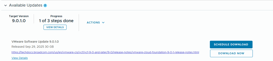
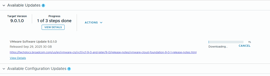
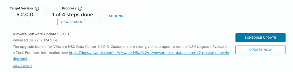
We’ll schedule the download of the bundles to start immediately “Download Now”
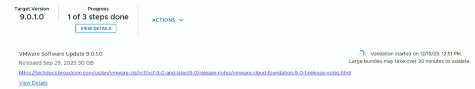
After the bundle is downloaded, the validation starts
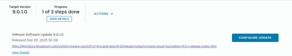
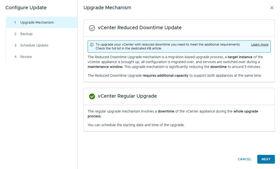
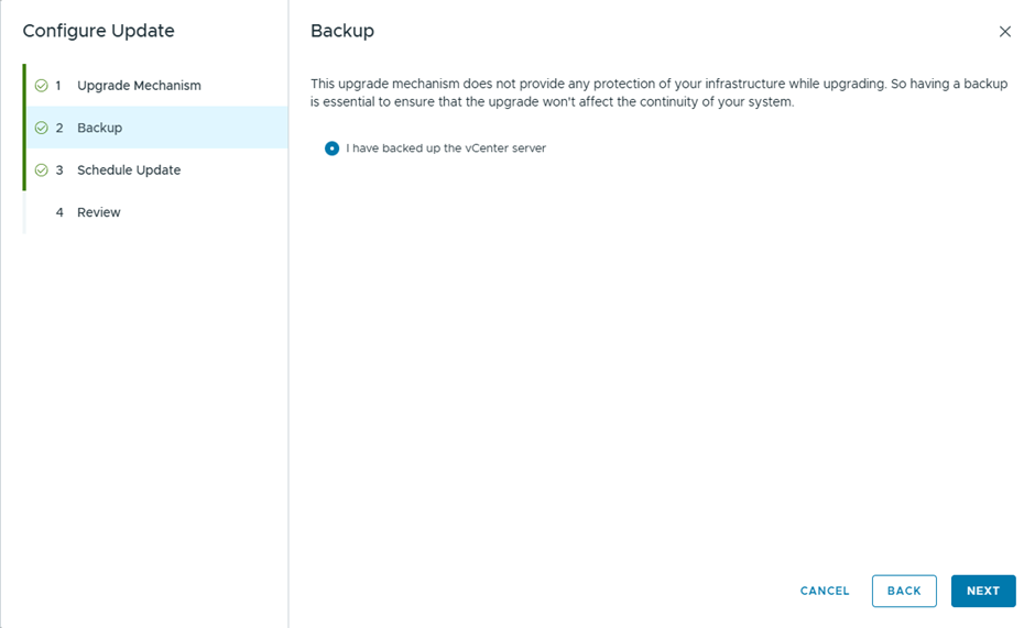
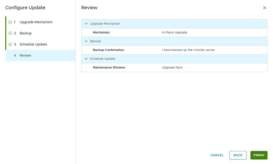
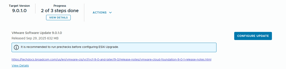
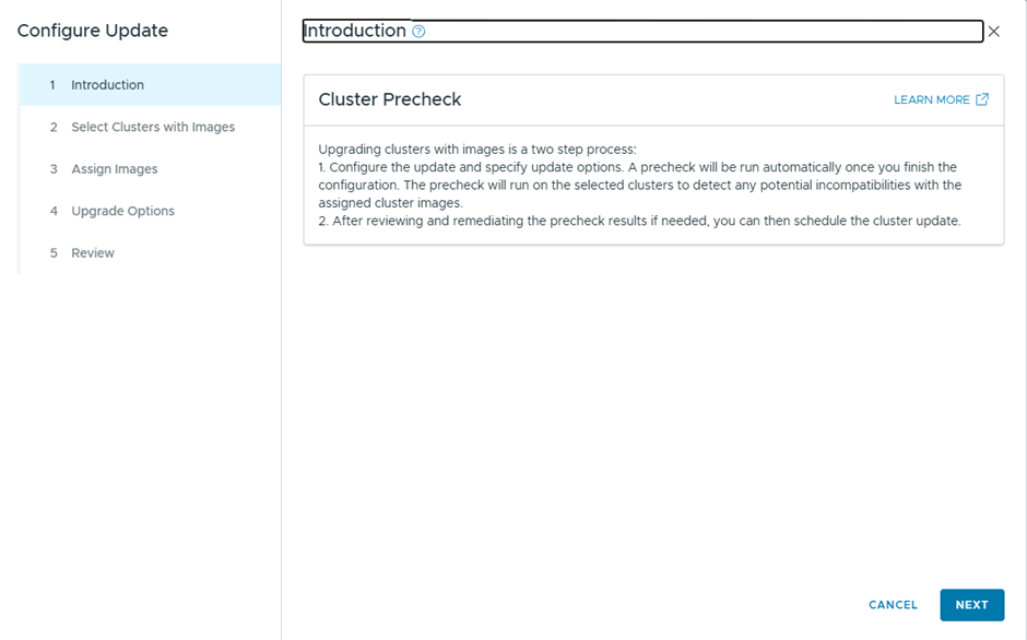
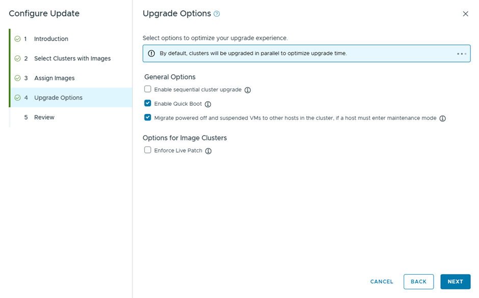
Then we configure the update
Since this is a lab, I didn’t take a backup , but in production you better take 🙂
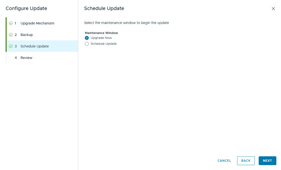
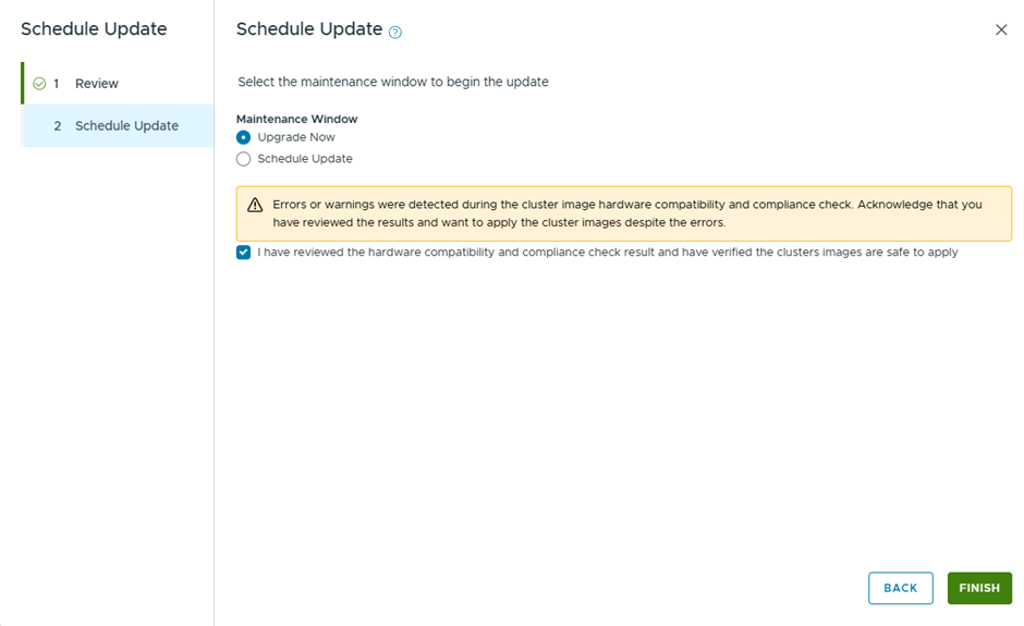
Select Upgrade now, to start the vCenter Upgrade instantly
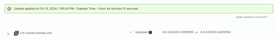
vCenter is now upgraded successfully
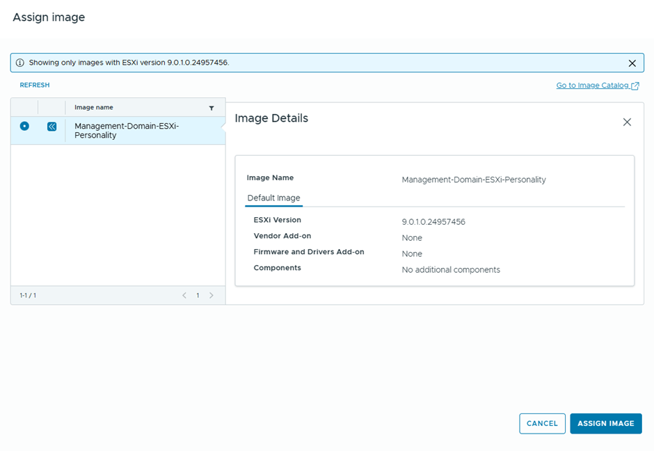
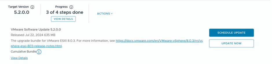
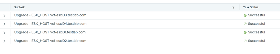
Final step , is to upgrade ESX, will download ESX 9.0.1.0 upgrade binaries and initiate the upgrade
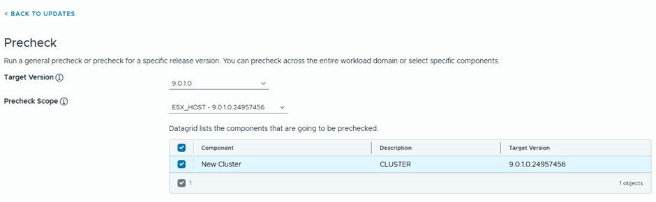
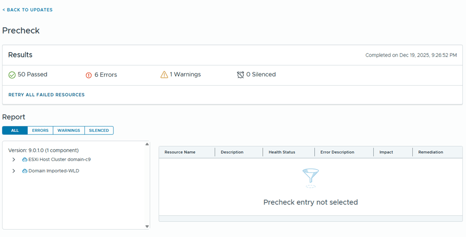
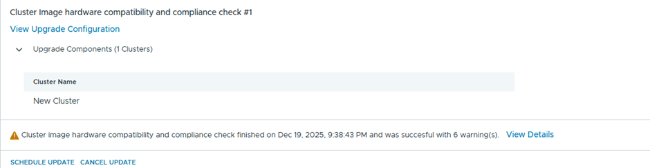
After the upgrade bundle is downloaded, now I’ll be running the prechecks
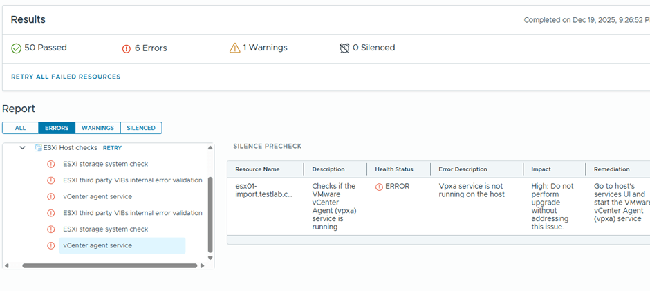
6 errors are showing
Well, I believe most if this errors might be related to having a nested environment, I’ll just proceed with the ESX upgrade and see what happens 😊
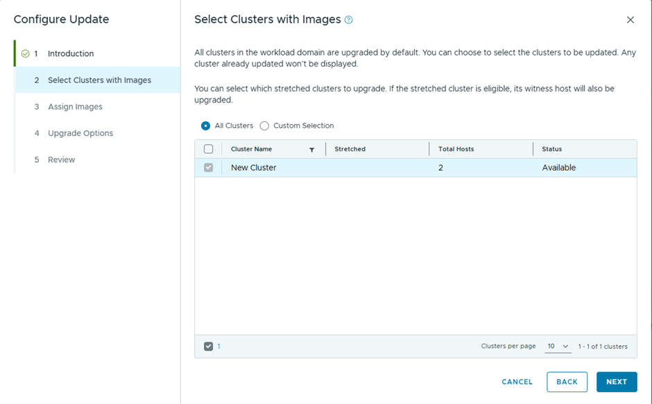
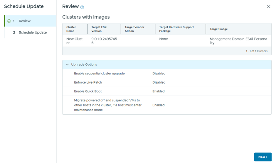
Only one cluster to upgrade
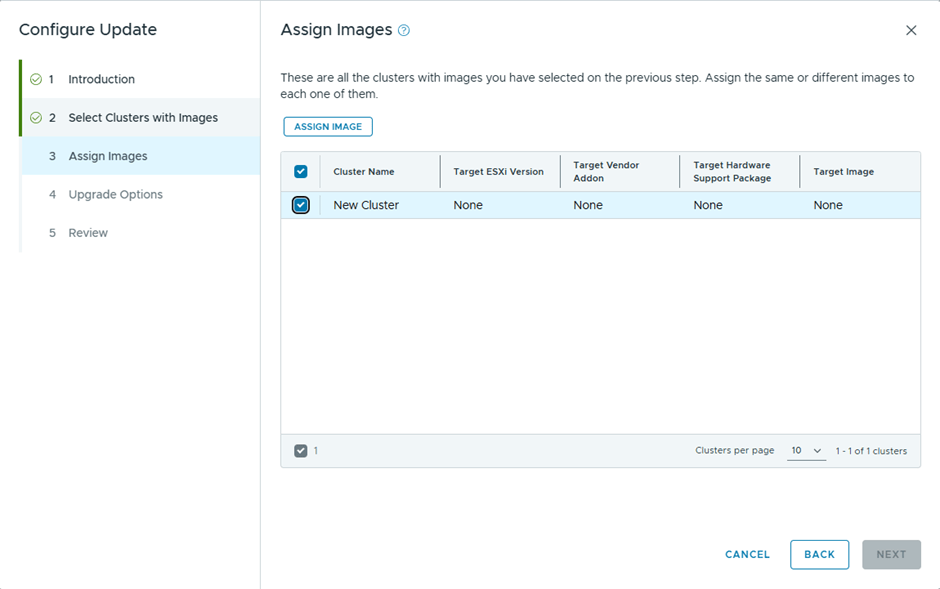
I’ll assign the image used by the management domain cluster
Will go with the quick boot option, instead of live patch
In the previous blog, we upgrade the vCenter to be imported, to 9 , so we can deploy NSX 9 and use it in a simple mode ( single node)
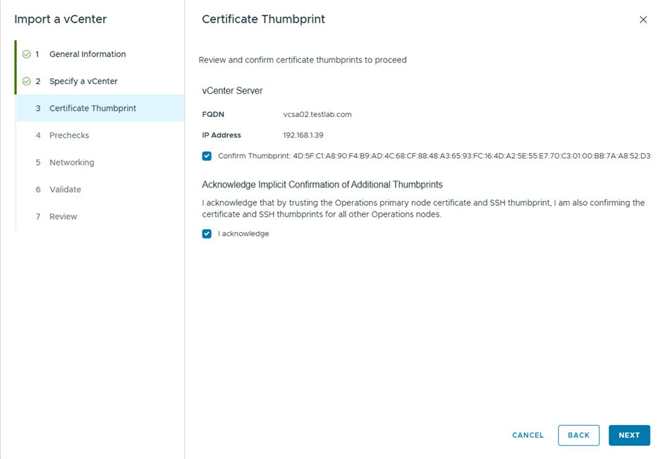
No running the import wizard again, we got this error
Which after increasing the MTU on the vDS got sorted
Now after the wizard page finished, got a different error
Checking the log file
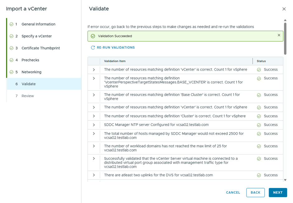
It was an incorrect DNS config from my end, however the validation in the wizard passed without highlighting it , after fixing the DNS , the import started to progress
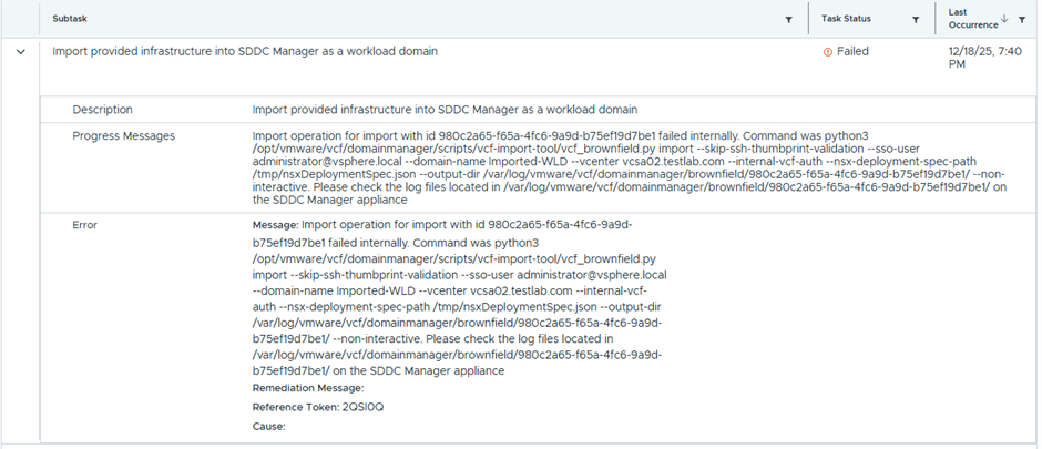
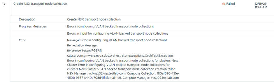
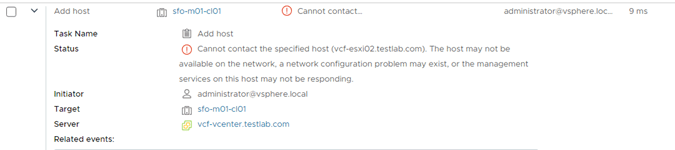
This time got a new error
The reason was that an LCM image pushed from and was stuck in this task
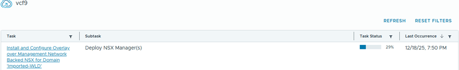
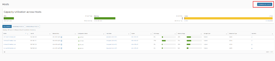
That’s because the imported ESX hosts didn’t have DNS configured, but after sorting this, the import was successful, this screenshot is from SDDC Manager
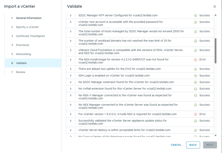
In the previous blog, we saw a couple of errors related to the requirement to install NSX 4.2.3 as well as that vCenter version <8 is not compatible with single Node NSX also upon checking the interoperability matrix , vCenter 8.0.3 is not supported with NSX 9.0.1 for greenfield deployments ( Link is in reference), so in this blog we’ll remediate this by upgrading the vCenter to be imported to version 9
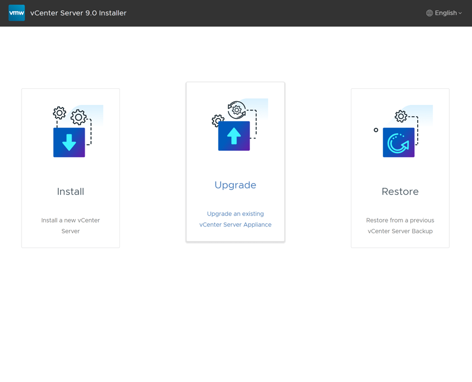
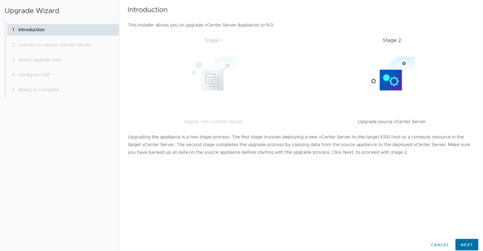
I downloaded vCenter 9.0.0 iso, and ran the UI of the installer, which is divided into two steps, deploying the appliance then migrating the data to the new appliance
Select Upgrade
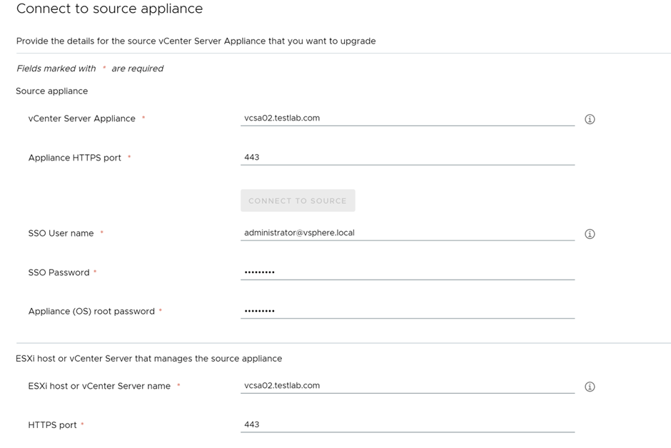
First step is to deploy a brand new appliance
Specify the source vCenter details
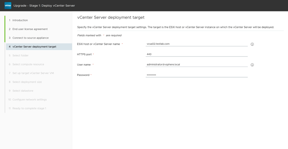
specify the destination were vCenter will be deployed
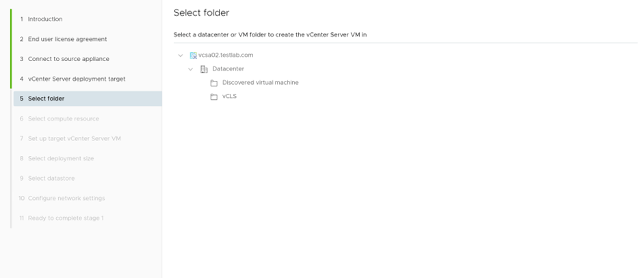
Select the folder and compute cluster
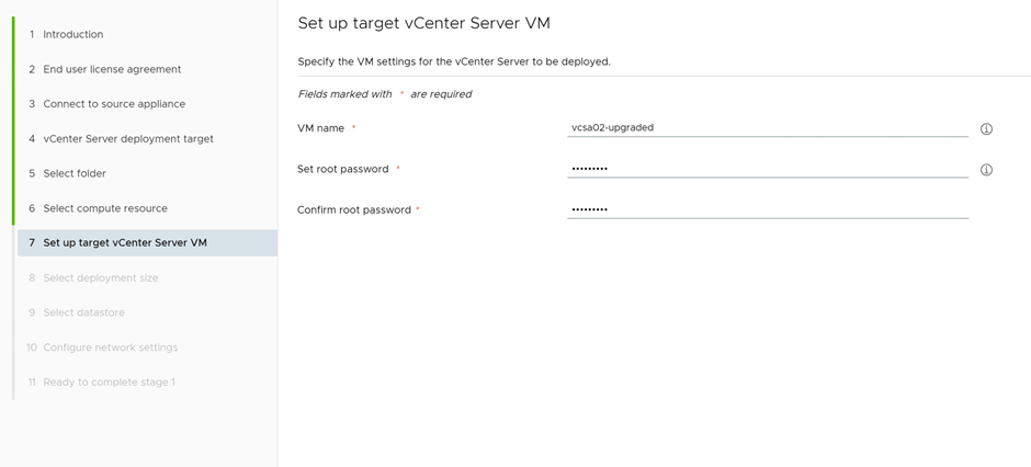
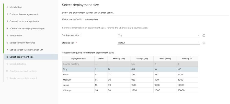
Provide the details of the vCenter to be deployed
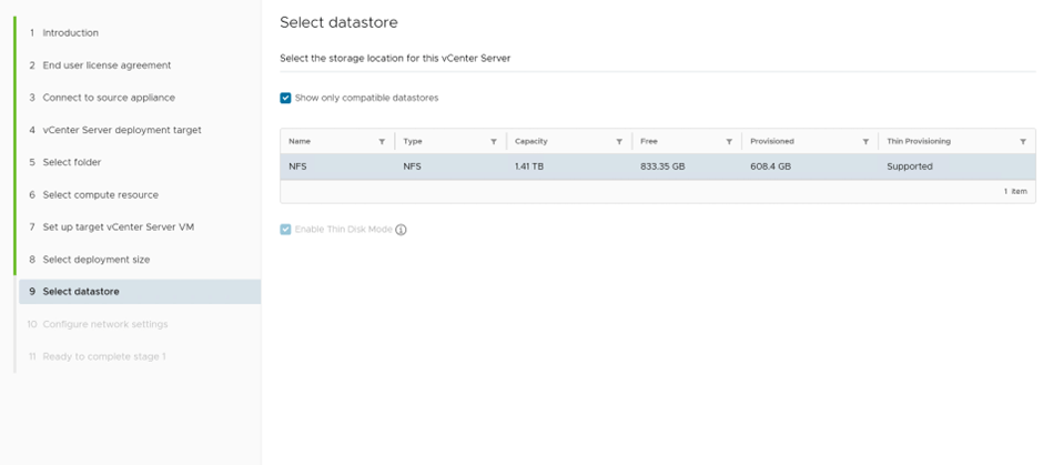
Select the datastore
Missed the screenshot of the network settings, but a temporary IP is requried for the upgrade
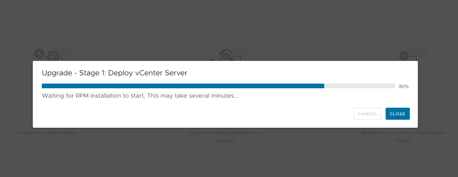
First stage, vCenter appliance is deployed
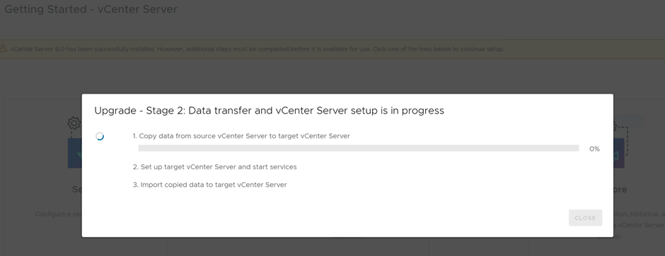
Now proceeding with stage two, which is copying the data from source vCenter to deployed vCenter
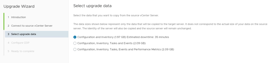
Since this is a lab environment, we’ll select upgrade configuration and inventory only
Upgrading Stage 2, in progress
Finally vCenter is upgrade to 9.0.0.0
Now, we’ll proceed in part 3 of this series, with importing the vSphere environment, after vCenter upgrade
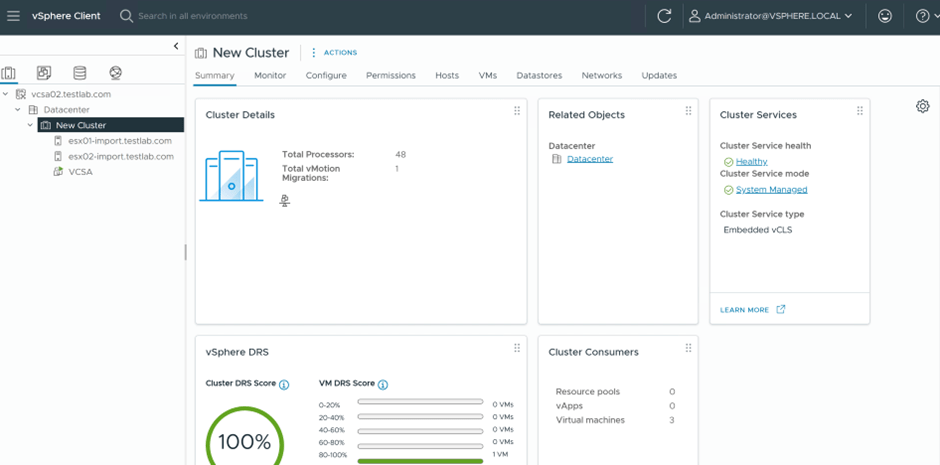
With the release of VCF9, lots of customers, have existing vSphere environments and would like to manage this environments under VCF Operations in VCF9 , in the below blog, we’ll go through importing a simple vSphere 8.0 update 3 environment under VCF Ops.
The existing environment to be imported has the following components:
vCenter 8.0 u3 (running on the same cluster
2 ESX hosts 8.0 u3
NFS Storage, Truenas
Lifecycle image is applied to both hosts
VCF 9.0.1
Single Management Workload Domain
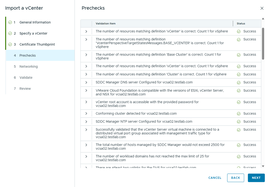
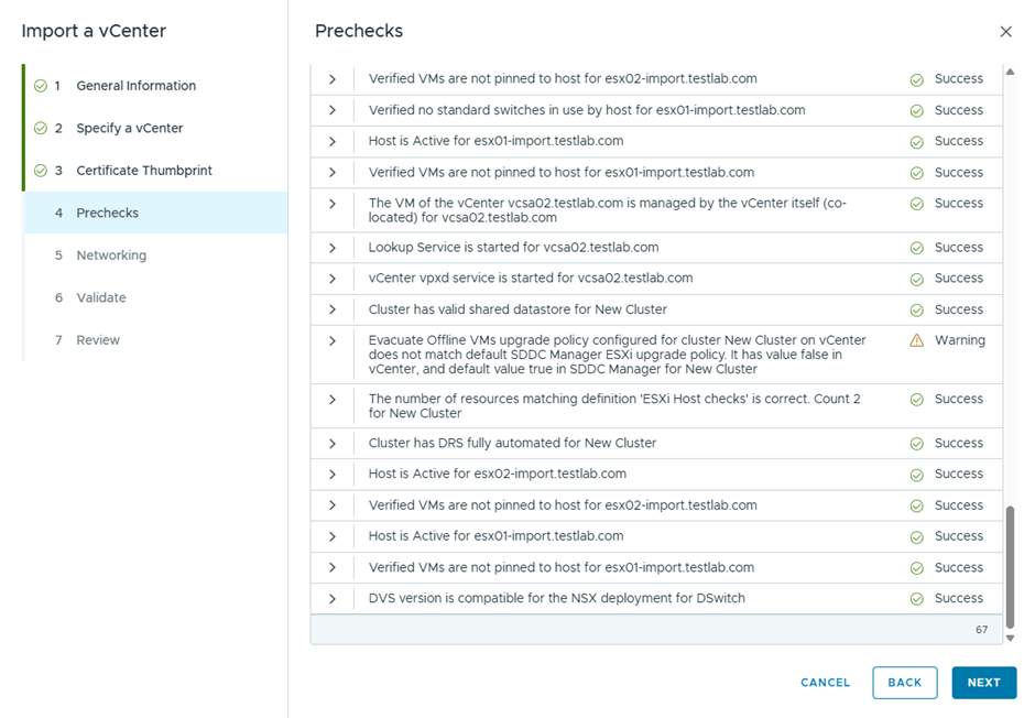
Below are the steps to import this vSphere 8 environment, under VCF 9 using VCF Ops
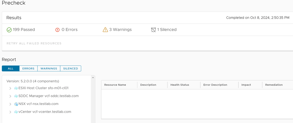
Following the previous blog where we uploaded all the bundles of to upgrade the VCF Management Workload Domain offline, I started running the prechecks for the upgrade and the below was the result:
Since this is a test and nested environment, I silenced the precheck alarm
In this blog we’ll discuss how to use the offline bundle transfer utility of VCF to upload install bundles to SDDC Manager in order to prepare for a VCF upgrade from VCF 5.0 to VCF 5.2, the offline bundle transfer utility is useful in case the SDDC manager doesn’t have internet access which is the case in air gapped environment.
The pre-requisites below are required for running the utility:
A Windows or Linux computer with internet connectivity (either directly or through a proxy) for downloading the bundles
The computer must have Java 8 or later
A Windows or Linux computer with access to the SDDC Manager appliance for uploading the bundles
To upload the manifest file from a Windows computer, you must have OpenSSL installed and configured ( what I did is I copied the files required to the SDDC Manager appliance using WinSCP after downloading them using the utility, this will be later explained)
First step I downloaded the bundle transfer utility from Broadcom Customer Support Portal
There Utility tool will be used in 2 locations, the PC where the manifest and compatibility files are downloaded as well as in the SDDC Manager,
So first is to extract the OBTU in my PC, which looks like the below:
Second to upload it to the SDDC Manager appliance via WinSCP
I copied it in the same location as suggested in the official documentation where I followed the below steps:
mkdir /opt/vmware/vcf/lcm/lcm-tools
tar -xvf lcm-tools-prod.tar.gz
cd /opt/vmware/vcf/lcm/
chown vcf_lcm:vcf -R lcm-tools
chmod 750 -R lcm-tools
One issue I was failing on using the utility from my PC was this :
Which I fixed by modifying by changing the default Java 8 installation location to a different folder than the default and modifying the JAVA_HOME environmental variable in my Windows PC
We need to download 3 files from the depot which are
Manifest file
Compatibility data
vSAN HCL file
To download the manifest file:
To download the compatibility data file:
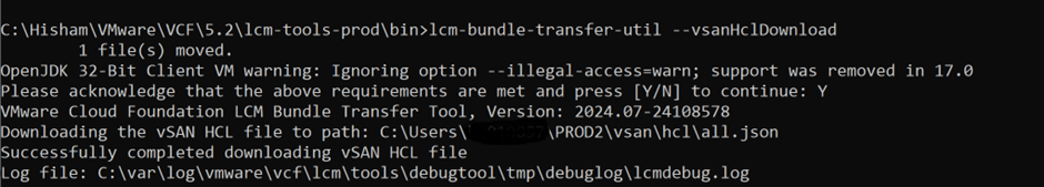
To download the vSAN HCL file:
Finally download the install bundles, I’m upgrading my lab from VCF 5.0 to VCF 5.2 so below are the steps I followed to download the install bundles
Using this command “lcm-bundle-transfer-util –download –outputDirectory C:\Hisham\VMware\VCF\5.2 –depotUser xyz@gmail.com –sv 5.0.0.0 –p 5.2.0.0”
And I selected All, notice here that Avi Controller is now available as part of the VCF 5.2 BOM is this is a new feature to lifecycle Avi Controllers from SDDC Manager ( this is available in VCF 5.2) previously it was a manual installation.
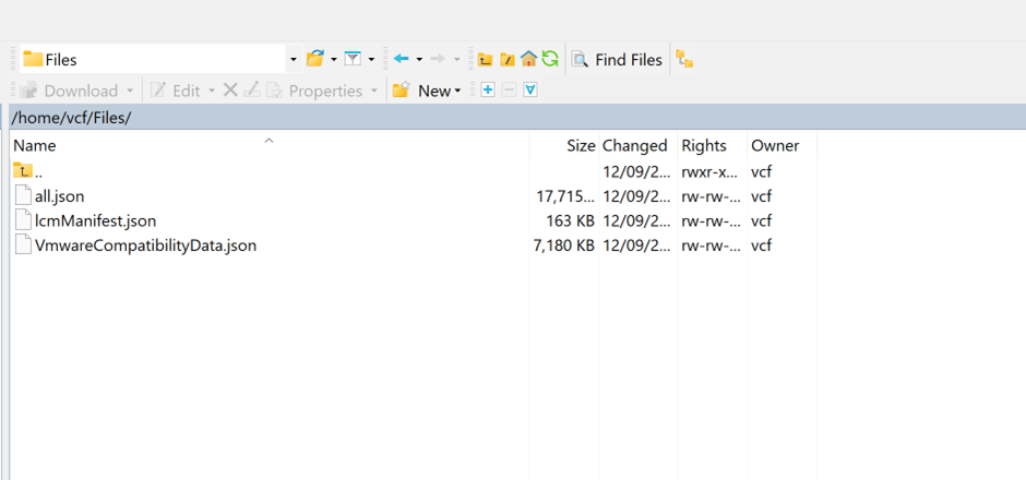
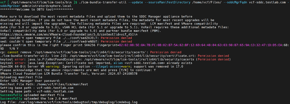
Next is to update the manifest file and Compatibility Matrix file in the SDDC Manager appliance. I uploaded the 3 files downloaded in the previous steps to the SDDC Manager appliance
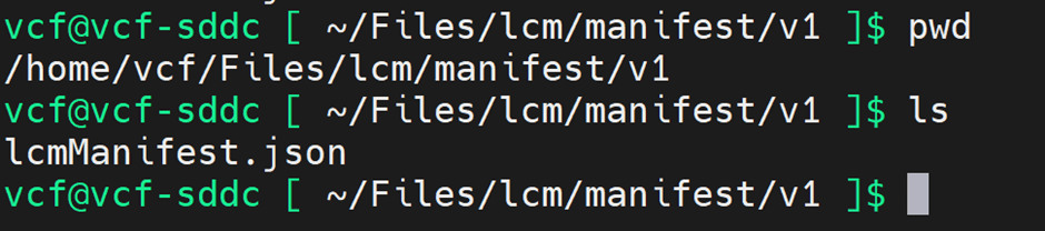
To update the sourceManifest file , I ran the below command in the SDDC Manager appliance, however I used to get couple of unexplained failures prior to that and the reason is the path of the file need to look something like the below
Not sure the reason behind it, but it had the same path when I downloaded it on my PC so I followed the same path.
Next, I did the same for the compatibility matrix file:
And when I tried to update the vSAN HCL file I got the below error:
ERROR: Cannot upload vSAN HCL to SDDC Manager versions below 5.1.0.0 so probably the one downloaded was not up to date,
Last but not least is to upload the offline bundles downloaded earlier to SDDC Manager
However I noticed when trying to update all bundles on SDDC Manager that only NSX gets uploaded, so instead I uploaded each bundle at time, not sure the reason behind this.
As per the below, the offline bundles are uploaded successfully to the SDDC Manager:
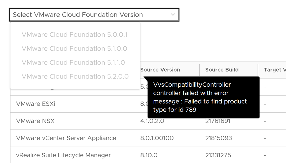
On clicking Plan for Upgrade the below message was showing:
The VMware Cloud Foundation deployment process is referred to as bring-up. You specify deployment information specific to your environment such as networks, hosts, license keys, and other information in the deployment parameter workbook and upload the file to the VMware Cloud Builder appliance to initiate bring-up of the management domain.
During bring-up, the management domain is created on the ESXi hosts specified in the deployment parameter workbook. The VMware Cloud Foundation software components are automatically deployed, configured, and licensed using the information provided. The deployment parameter workbook can be reused to deploy multiple VMware Cloud Foundation instances of the same version.
The following procedure describes how to perform bring-up of the management domain using the deployment parameter workbook. You can also perform bring-up using a custom JSON specification
In this blog, I’ll prepare VCF 5.0 bringup in a nested ESXi environment.
Software installed:
Cloud builder 5.0.0
ESXi 8.0 update 1a
Memory: 128 GB RAM
Deployment parameters workbook VCF 5
Infrastructure pre-requisites:
I’m using opnsense as the gateway for the below networks:
Management
vMotion
vSAN
Host Overlay
Forward and reverse DNS records for:
Cloud Builder
4 ESXi hosts
1 NSX manager (the reason here, is that I’m using one NSX manager, I modified the JSON file for bringup to include one NSX manager only)
NSX manager VIP
SDDC manager
vCenter
ESXi Preparation
4 ESXi hosts were installed with the below resources:
Storage:
40 GB hard disk for boot
26 GB for Cache
256 for capacity (2 & 3 are requirements for vSAN)
CPU: 20 cores, 10 cores per socket, which ends up with 2 sockets
Memory: 128 GB
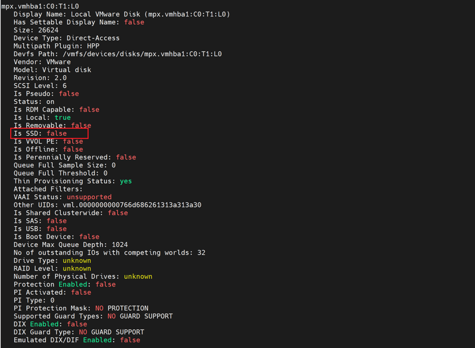
One more step here, I checked the hard disk for 26 GB and it didn’t show as SSD:
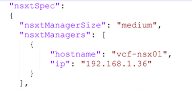
Since this is a lab environment, there is no need to use 3 NSX managers, I’ll only use one and to do so, I modified the JSON file generated from the excel file of the deployment parameter sheet, in order to do so , we need to convert the excel to JSON and then modify the JSON:
/opt/vmware/bringup/scripts/json-generator.sh my-vcf-deploy.xlsx my-vcf-deploy.json vcf-ems (The source file is the deployment parameter excel and the destination is the JSON file)
Now, the final step, which is deploying the cloud builder VM and importing the modified JSON file (with one NSX Manager), I’ve all management IPs in the same subnet (192.168.1.0/24) with VLAN 0,
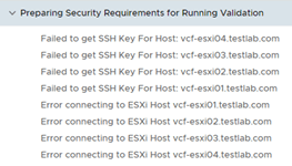
I faced this issue on reviewing the pre-requisites page
Failed to get SSH Key for Host
This is due to incorrect password configured in ESXi host, versus what was configured in the deployment parameter sheet, once this is configured, the verification passed except one issue
Which I ignored as this is a lab environment
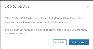
Now clicked on Deploy SDDC and left the deployment running,
After sometime, I faced the below errors:
The log file where I checked the above error was :
/var/log/vmware/vcf/bringup/vcf-bringup-debug.log
I checked around and found out that from vCenter I can’t ping any of the 3 hosts, only the host where vCenter is deployed is reachable form vCenter,
Since originally I cloned 3 ESXi VMs from the first one, I suspected issue with UUID which I reset
Followed this and still was the same issue, so I re-installed the entire ESXi VMs and then the error was bypassed
Hit this error:
Apparently the time it takes for deploying NSX manager is more than the wait time from Cloud builder VM, so I suspended the cloud builder VM and waited till NSX manager loads
After NSX Manager loaded, I resumed the cloud builder VM
Starting NSX 3.2.2 release the Sub-Transport Node Profile within a Transport Node Profile feature was created in order to support Stretched L2/L3 clusters and stretched vSAN clusters
Sub-TNP is basically a template to be applied to Sub-Clusters to be prepared for NSX with a configuration different than the one used in one TNP , one use case is having ESXi hosts under the same clusters in different sites, however the host TEP network is not available/stretched across the two sites, in this case a Sub-TNP can be applied to the Sub-Clusters of the second site for instance with different host TEP which means different IP pools and a different VLAN, without affecting the overlay segment communication across the two stretched vSphere cluster.
A sub-TNP can only override the following fields of a host switch: VDS Host Switches ID, uplink profiles and IP assignment.
In this blog we’ll demonstrate that, I have a vSphere cluster with 2 ESXi hosts, esxi03 and esxi04, assuming that esxi04 is in a different site and the host TEP subnet used for esxi03 is not available at the second site, so we’ll create 2 different uplink profiles, 2 different IP Pools.
vSphere Cluster:
Network Pools:
The first pool will be referred to in the Transport Node Profile used for esxi03:
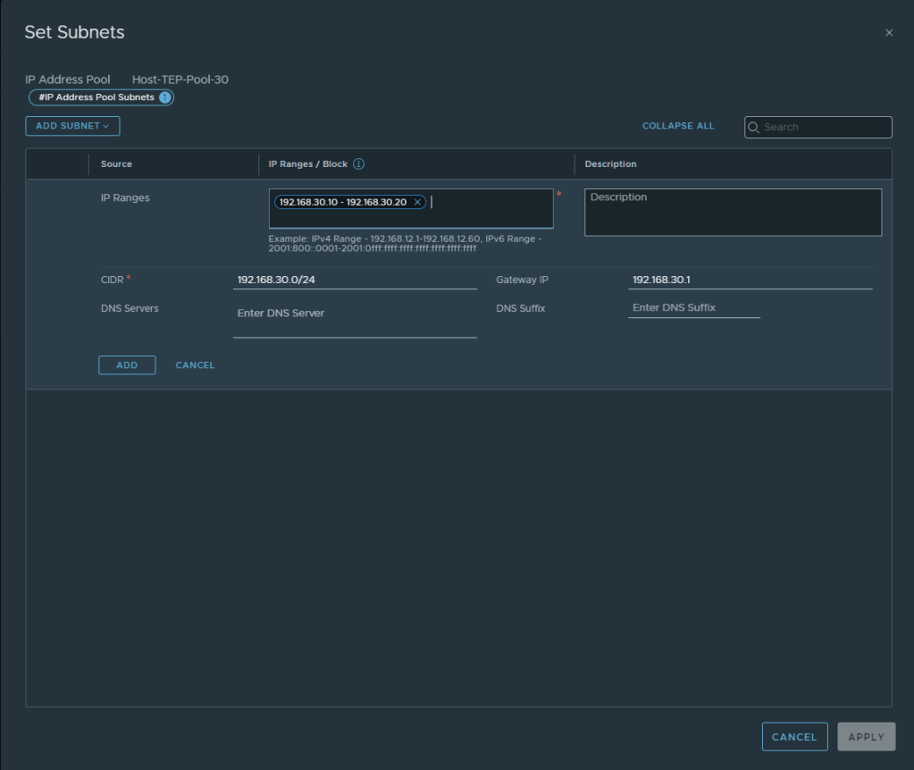
The second IP Pool will be referred to in the Sub-TNP used to prepare esxi04:
IP Pools
The first IP Pool will be referred to in the Transport Node Profile used for esxi03:
The second IP Pool will be referred to in the Sub-TNP used for esxi04:
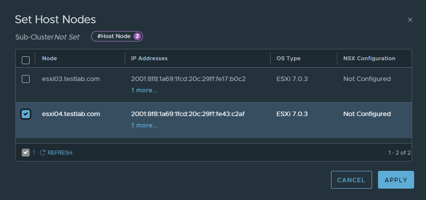
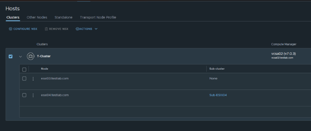
We’ll create a Sub-Cluster and add to it esxi04:
You’ll notice here that the sub-cluster was added for esxi04
Transport Node Profile:
Notice here the uplink profile and host TEP IP pool used are for esxi03
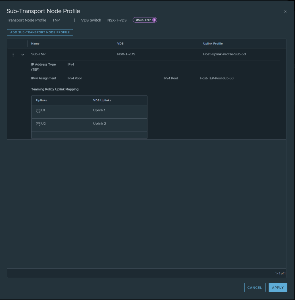
However in the Sub-TNP the below configuration was used:
Next step, is to prepare the cluster using the TNP and the Sub-TNP:
Notice here that the we are applying the Sub-TNP to the Sub-Cluster
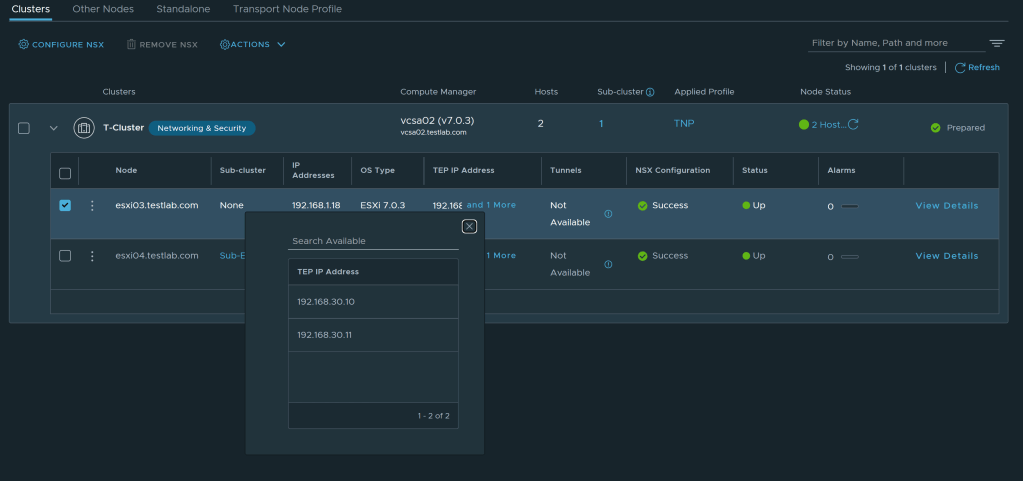
Let’s check the host TEPs assigned to esxi03
Let’s check the host TEPs assigned to esxi04
Testing TEP to TEP reachability
So to conclude, it’s a nice feature to have, in case of underlay networking restrictions.
The NSX Advanced Load Balancer supports improved and more flexible methods for upgrading the system. The Controller supports all the upgrade workflows through the UI
First Step , is to download the target version, currently I have NSX ALB version 21.1.5 and I I’m upgrading to 22.1.3
Figure 1 Target Version
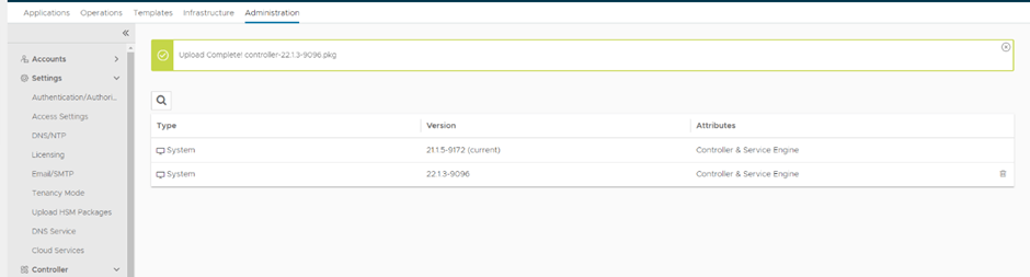
Then, login to existing NSX ALB Controller and upload the .pkg file, Go to Administration –>Controller
–>Software then upload the .pkg file from Computer
Figure 2 Uploading .pkg file
Upload will take some time to complete,
Figure 3 Upload In Progress
Figure 4 Upload Completes
Now go to Administration–>System Update–>Upgrade
Figure 5 Upgrade Process
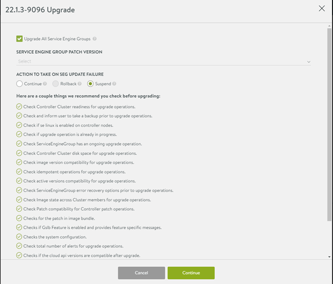
The next window shows pre-upgrade checks as well as Service Engine option to upgrade or stay at the current version, in my lab I’m upgrading all,
Figure 6 Upgrade Prechecks
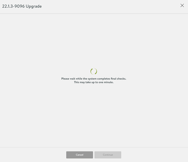
The Controller will take some time to do the final checks
Figure 7 Upgrade final checks
The Controller will not be accessible during the upgrade process
Figure 8 Controller temporary unavailable
Finally after 5-10 minutes the Controller was up and the Service Engine Groups are upgraded successfully