NSX supports static routing as well as dynamic routing protocols to provide connectivity to workloads hosted in vSphere environment to the outside word, in case of dynamic routing, neighbor failure detection, or next hop reachability can be determined with keepalives, for example in case of OSPF , it’s the hello and dead intervals and in BGP it’s the keepalive messages, BFD can be used with dynamic routing protocols to support faster failover times.
Static routing can be configured on a T0 gateway, toward external subnets with a next hop of the physical upstream device. To protect the static routes, BFD is highly recommended to detect the failure of the upstream device.
The timers depend on the edge node type, edge VMs support minimum of TX/RX 500 ms and baremetal edges support a minimum of 50 ms.
In this blog, we’ll configure T0 with static routing and BFD with some failover scenarios while testing N/S reachability, the below diagram is the architecture we’ll reference in this blog post.
Figure 1 Edge node Design:
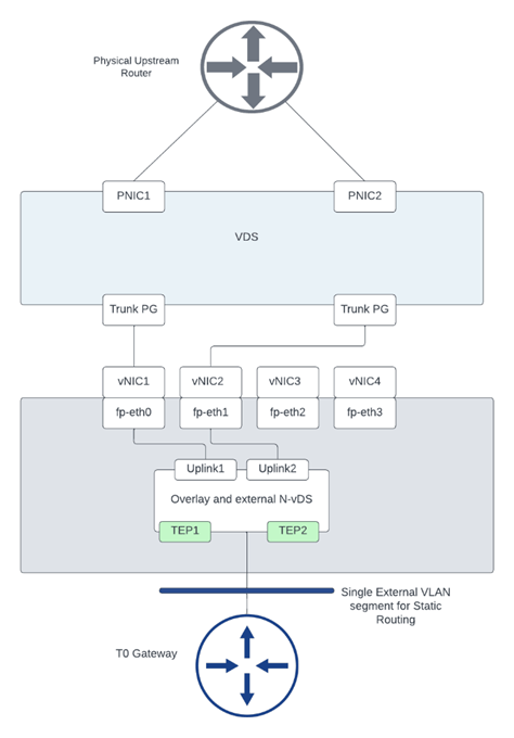
Figure 2 T0 logical design:

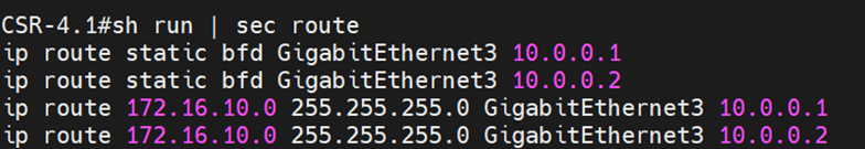
This is a snippet from the configuration of the upstream device:
The interface gigaethernet3 configuration

This BFD configuration matches the BFD configuration used in defining a BFD peer under T0 shown later.
The static routes configured with BFD towards the edge nodes 1 and 2:
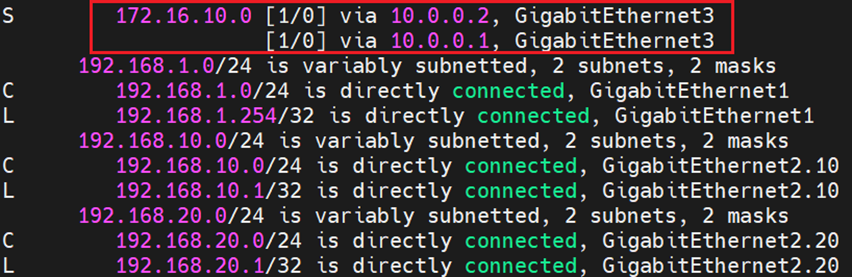
And finally the routing table which shows ECMP configuration of the static route pointing to the overlay segment in NSX:
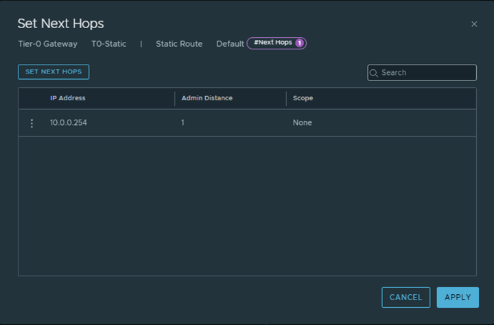
From NSX, the below configuration was made:
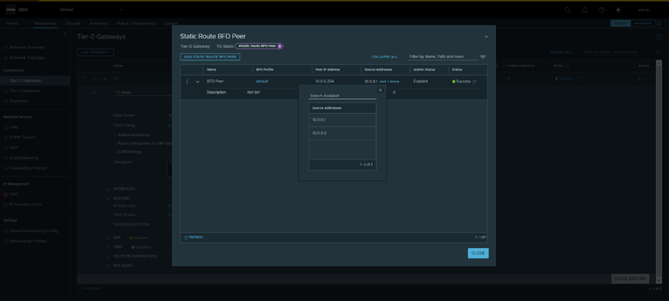
The default BFD Profile was used, which has the same timers as the ones configured in Cisco:

And Finally a default route was configured from T0 gateway pointing towards the Physical upstream device:

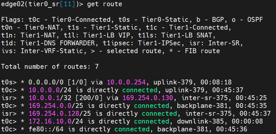
From Edges CLI, let’s validate the routing table of each:
Edge node 1:

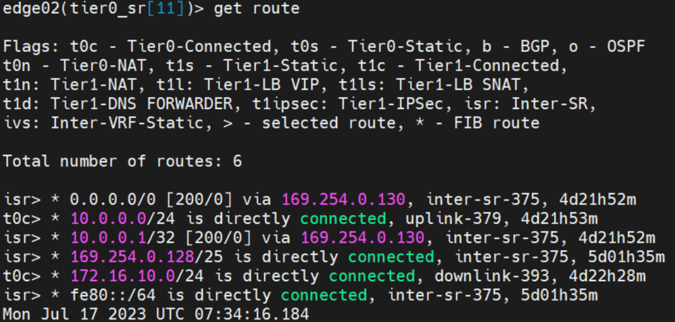
Edge Node 2:
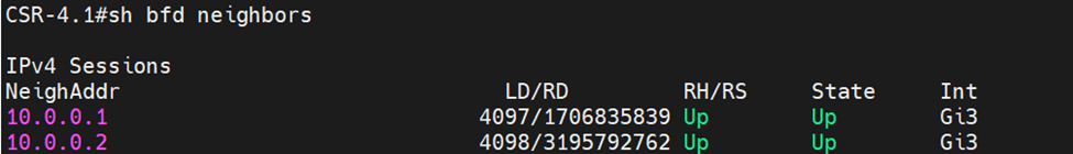
Let’s validate that BFD is up before testing failover scenarios:
From Physical upstream device:
From each edge node:
Edge Node 1:

Edge Node 2:

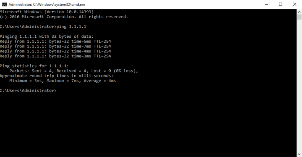
Testing N/S reachability before failover
I’ve created a loopback on the physical upstream device with ip 1.1.1.1/32, to test connectivity we pinged from a test VM on the overlay segment in NSX:
To test failover, I’ll change the IP of the uplink interface of Edge node 1 to 10.0.0.3 instead of 10.0.0.2
From the upstream device, the routing table has changed:

Let’s examine the routing table from each edge node:
Edge Node 1:
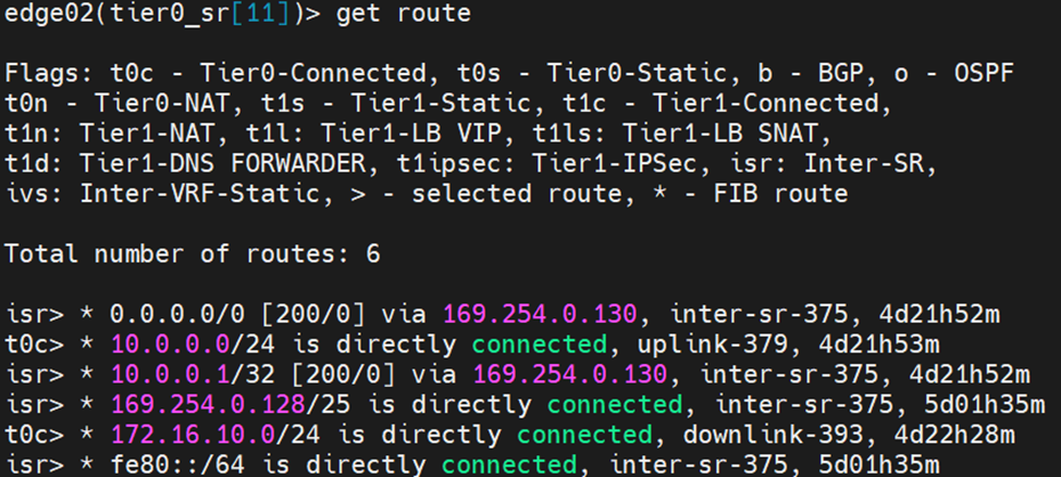
Edge Node 2:
Notice here that edge node 2 learnt the default route from the isr, the reason is explained as per the reference design guide below:
When Inter-SR routing is enabled by the user, an overlay segment is auto plumbed between SRs (similar to the transit segment auto plumbed between DR and SR) and each end gets an IP address assigned in 169.254.0.128/25 subnet by default. An IBGP session is automatically created between Tier-0 SRs and northbound routes (EBGP and static routes) are exchanged on this IBGP session
After correcting the uplink IP of Edge Node 2, you can see the default route in the routing table pointing to the physical device

