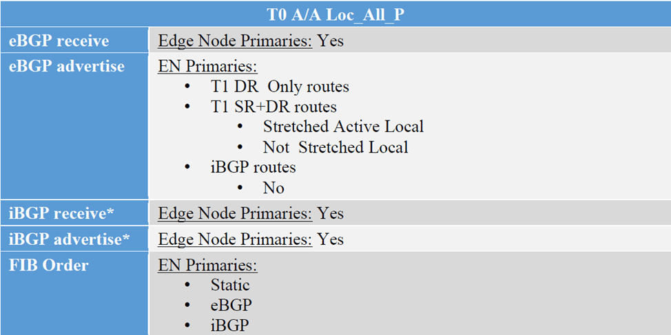
In this final blog for NSX Federation, we’ll discuss the third configuration option for T0 which is “Active/Active Location All Primary” , this option is for T0s without services, VMs egressing from their location, will send the traffic to their local Edge Nodes, supporting local egress. The below is the route exchange between T0 A/A All Primary and the upstream device,
However in this blog, we will go with T1 with custom span and monitor the traffic flows
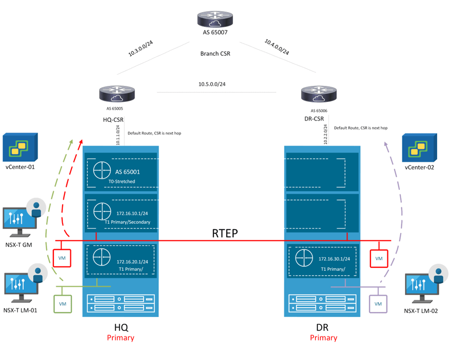
Looking back at the previous topology, the mode of T0 is changed and also added 3 T1s instead, where 2 T1s are location specific having only one primary location and another T1 with custom span, having HQ as primary and DR as secondary

First Change the mode of the T0 to “Mark All locations as Primary”:

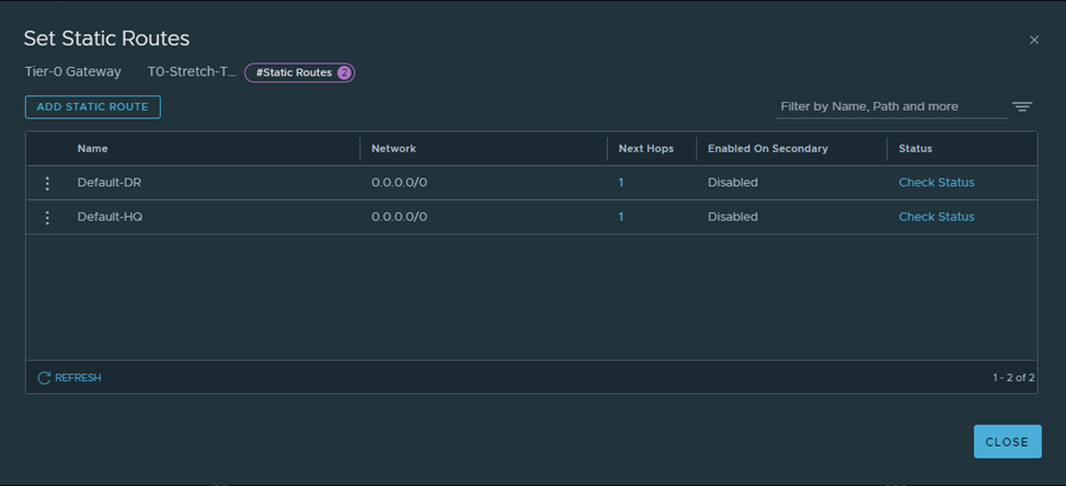
Next, let’s create Default route on each location pointing to the corresponding CSR:
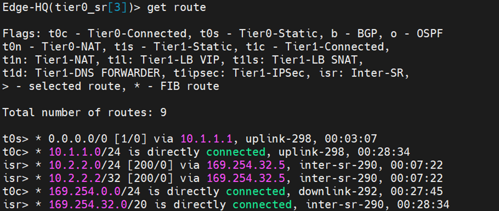
Let’s verify from edge nodes:
HQ:
DR:

Let’s Now create the three T1s, according to the diagram above,
T1-HQ with HQ only as the primary location:

T1-DR with DR only as the primary location:

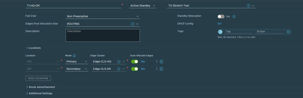
Finally Create the last T1 with HQ as Primary and DR as Secondary:
After Creating the segments and connecting them to their respective T1s accordingly:

Let’s verify the span of each T1 created from Edge nodes in HQ and DR:
Edge Node in HQ:

As you can see, T1-HQ and T1-HQ-DR are existing here due to their span which is HQ and DR respectively
Edge Node in DR:

As you can see, T1-DR and T1-HQ-DR are existing here due to their span which is HQ and DR respectively
Let’s verify from the edge nodes the forwarding table of each T1 SR component:
T1 HQ:
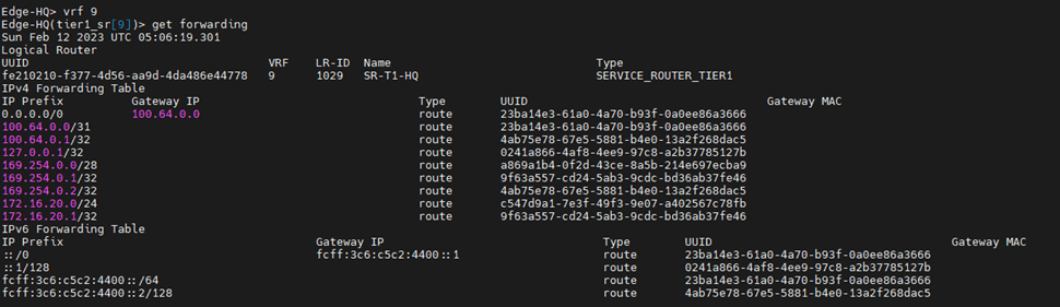
You can see that this points to T0 DR
So if a VM in HQ is connected to a segment which is connected to T1-HQ communicates South North, the traffic flow will be:
T1-HQ DR –>T1-HQ SR–>T0 Stretched DR–>T0 Stretched SR–>Upstream Device
For T1 HQ-DR SR, we will verify the forwarding table from edge node in HQ and edge node in DR:
HQ edge node:

So if a VM in HQ is connected to a segment which is connected to T1-HQ-DR communicates South North, the traffic flow will be:
T1-HQ-DR DR –>T1-HQ-DR SR–>T0 Stretched DR–>T0 Stretched SR–>Upstream Device
DR edge node:

Notice here, the default route on the T1-HQ-DR SR component is learned from 169.254.32.2 which is the Intersite Transit Subnet field. This subnet is used for cross-location communication between gateway components
So if a VM in DR is connected to a segment which is connected to T1-HQ-DR communicates South North, the traffic flow will be:
T1-HQ-DR DR–>T1-HQ-DR SR–>Cross Site (RTEP Encapsulation )T0 Stretched DR–>T0 Stretched SR–>Upstream Device
We will do packet walks later in this blog
let’s check the forwarding table for Lets check the forwarding table of T1-DR

So if a VM in DR is connected to a segment which is connected to T1-DR communicates South North, the traffic flow will be:
T1-DR DR –>T1-DR SR–> T0 Stretched DR–>T0 Stretched SR–>Upstream Device
Finally, let’s check the routing table of T0 stretched SR component in each site:
HQ:

First 2 routes are advertised from the two T1s, which have span HQ and HQ-DR , last highlighted route is known from iBGP (RTEP) between two sites.
DR:

First two routes are known from iBGP (RTEP) and the last one is known from T1-DR which spans DR only
So quoting from the multi-locations design guide, this is how the traffic flow will be from each site:

Let’s customize this in our topology instead
Let’s create the below static routes:
HQ-CSR:

DR-CSR:

After Redistributing into BGP, let’s do a traceroute from test VMs in each of the 3 segments to a loopback IP in the branch router.
Traceroute from a VM in HQ connected to a segment connected to T1-HQ-DR:
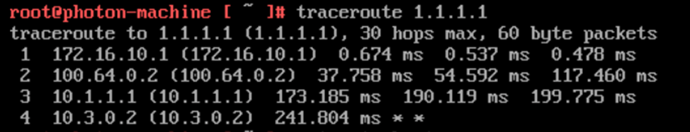
Traceroute from a VM in HQ connected to a segment connected to T1-HQ:

Traceroute from a VM in DR connected to segment connect to T1-DR:

Traceroute from a VM in HQ connected to a segment connected to T1-HQ-DR:
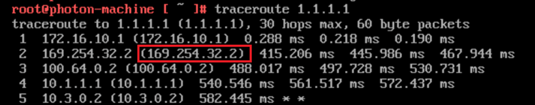
Notice here that the VM in DR site, crossed the intersite link to egress form HQ , this means any VM connected to a segment connected to T1 with custom span, will always egress from the site listed as primary in T1
References:
