NSX-T federation is of the two multisite solutions (NSX-T multisite is the other one) , it was introduced in 3.0 and recommended in NSX-T 3.1 onwards, it basically consists of one Global manager offering networking and security services to multiple locations, in each location there is one NSX-T local manager cluster.
In this blog, we will focus on one of the routing scenarios discussed in the NSX-T multilocation guide (referenced at the end), which is T0 A/S Loc P/S, but first we will go step by step how to setup federation between two sites, configure RTEPs, stretching segments and setup routing.
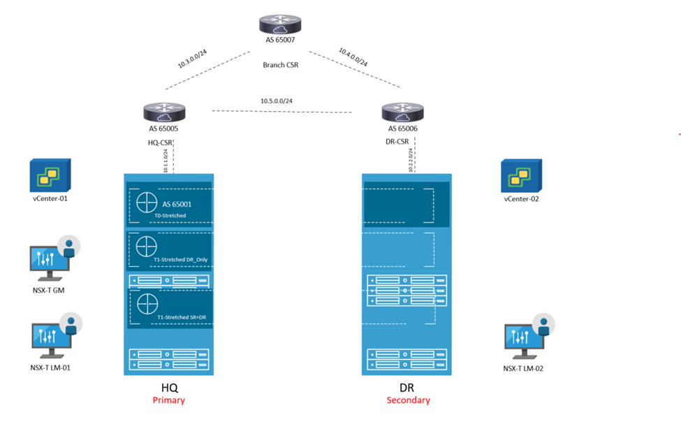
The below is the architecture which is used in this lab:
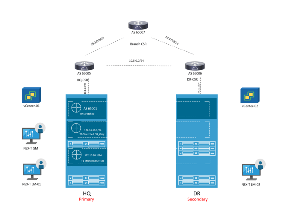
This set up consists of :
2 NSX-T Local Managers ( 1 at each site) version 4.0.1
1 Global Manager version 4.0.1 ( Not using Standby in this lab)
1 Edge node at each site
2 vCenters version 7.0.1
4 nested ESXi Hosts version 7.0.1
A couple of photon VMs for testing E/W , N/S traffic
3 CSRs ( 1 for each site and 1 branch router to demonstrate traffic flow)

The IP addressing is like the below:
Site-1:
Host TEP: 192.168.70.0/24
Edge TEP: 192.168.80.0/24
RTEP: 192.168.110.0
GW of the above resides on HQ CSR
Site-2:
Host TEP: 192.168.90.0/24
Edge TEP: 192.168.100.0/24
RTEP: 192.168.120.0
GW of the above resides on DR CSR
eBGP is already configured between the 3 CSRs
Below are the steps to configure federation, Global T0 in A/S location P/S
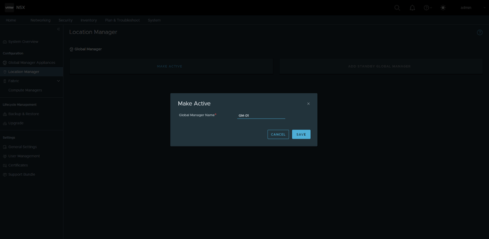
Configure GM in Site-1 as active:
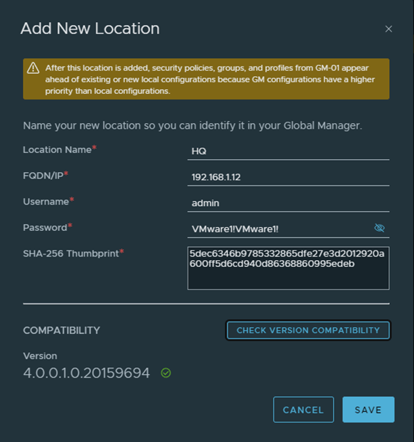
Add HQ as the first location , in order to do that, I got only the manager thumbprint as per the below, in a production environment, you should get the cluster api thumbprint using get certificate cluster thumbprint instead

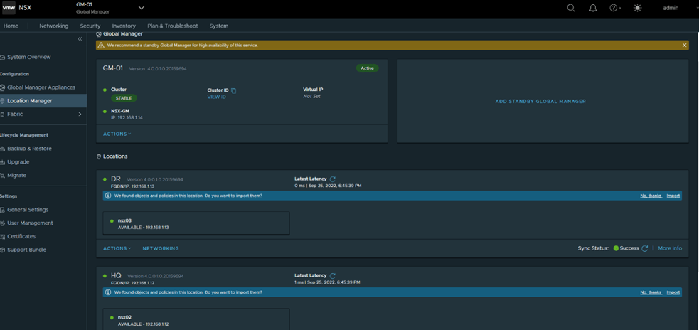
Similarly add DR as the second location and the final status after adding both locations
Next is to configure RTEPs, in HQ

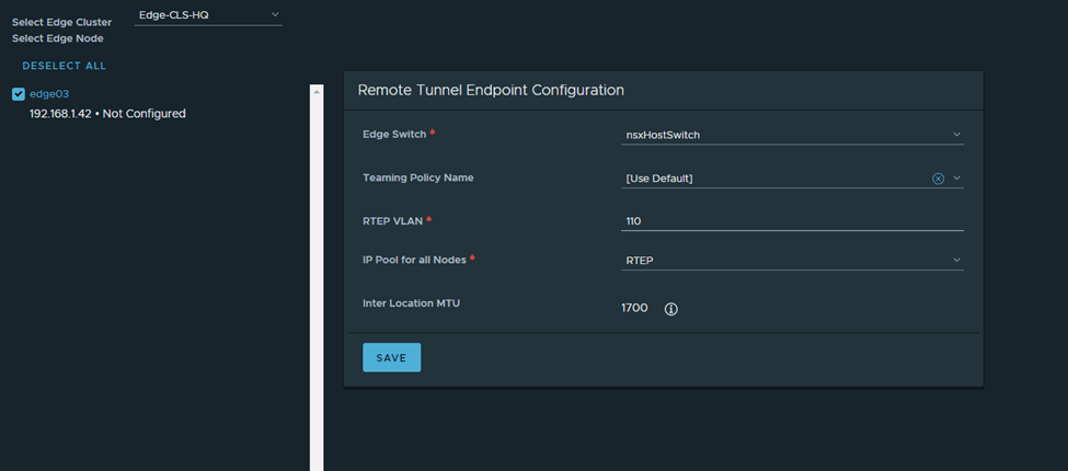
Note: The HQ and DR CSRs are routing the RTEP subnets between both sites in this setup
I’ll follow the same steps in DR:


Next, I’ll configure a stretched T0 as per the eBGP details in the diagram (reattaching)

Here you notice HQ is the primary location, DR is the secondary one and the HA mode is Active/Standby BGP neighbors are now up

I’ll get back to T0 in detail in a bit, but for now I’ll configure 2 T1s (1 T1 DR only and 1 T1 SR+DR),
Connect a segment to each and test connectivity
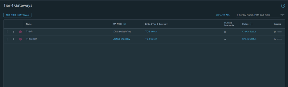
Verify from Edge nodes

Segment 172.16.10.1 will be connected to T1-DR
Segment 172.16.20.2 will be connected to T1-SR+DR
I’ve configured the CSRs to only advertise a default route only to the Stretched T0,
Let’s analyze the primary site edge node routing table

Route 1 : default route received from CSR
Route 2: this is the interface connected to T0 for BGP peering
Route 3:this is received from isr(iBGP, from the secondary site notice the admin distance)
Route 4:same to route 3
Route 5+6:the intertier T0 connected interfaces ( interfaces to which T0 DR connects to T1-DR and T1-DR+SR)
Route 7:this is the intra-tier subnet which is between T0 DR and T0 SR
Route 8: new subnet created in federation for intersite communication (iBGP)
Route 9 + Route 10: T1 connected segments
Let’s check the edge node bgp table

Let’s check from the CSR side in HQ
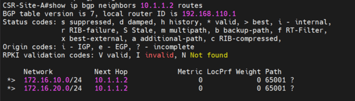
Let’s cross check this with the reference from the multilocation guide
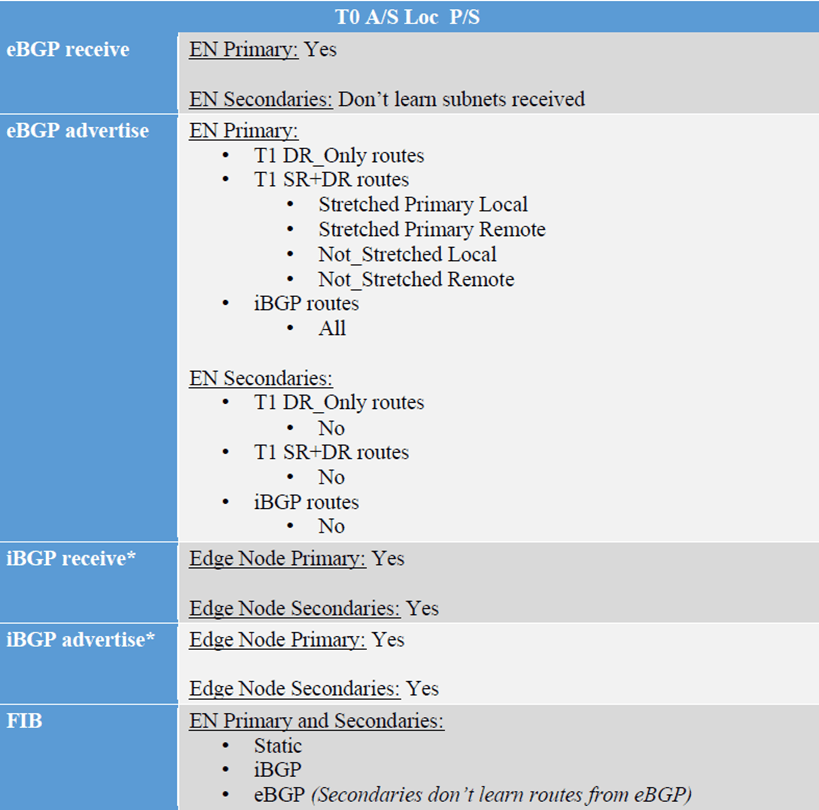
Primary edge node is :
Receiving default route from CSR –> eBGP receive
Advertising the T1-DR, T1-DR+SR –>eBGP advertise
Receiving iBGP (with lower local preference)–>iBGP receive
Advertising iBGP(directly connected subnets as well as BGP interfaces)–> iBGP advertise
Now let’s check the secondary edge routing table and advertised routes to CSR:


1-We are going to advertise a loopback of 1.1.1.1 from the branch router
2-Do a trace from a VM in the secondary site to the loopback and vice versa
3-Analyze the inbound and outbound traffic
From the branch router it goes the primary edge node

From the VM to the loopback of 1.1.1.1

This again shows that the egress and ingress traffic is from the Primary site/ HQ.
