I’d like to share with you this document, which is based on best effort approach for bridging between NSX-V to NSX-T which can be used as one of the migration approaches .As you know since NSX-V will be deprecated by January 2022, as a result we might be seeing a lot of customers migrating their current environments to NSX-T.
There are different methodologies for that, for example, in parallel upgrade, in place upgrade and so on. For the in parallel upgrade we can create cross connectivity between 2 NSX domains using bridging. Here we have two types of bridging, independent bridging and NSX-T only bridging.
Our focus in this document would be the 2nd type (NSX-T only bridging), which is deploying an NSX-T Bridge on NSX-V prepared hosts, which will be taking advantage of the decapsulation of VXLAN frames happening on the NSX-V hosts and encapsulating these into GENEVE.
We would make use of that, in case of migrating the workloads from NSX-V to NSX-T without affecting internal or external network connectivity; in the means of having the default gateway for a subnet as the DLR interface while the VMs of this subnet might be in the process of migrating between NSX-V to NSX-T, for instance we might have 100 VMs for a web subnet, 50 of them might be existing on NSX-V environment while the rest migrated to NSX-T, both will be using the DLR interface to communicate externally as well as the communication between VMs won’t be interrupted (since we are bridging here between Overlay and VXLAN), this situation is temporary till all VMs migrate to NSX-T environment then we can change the default gateway for a segment to be the T1 interface.
High Level Architecture
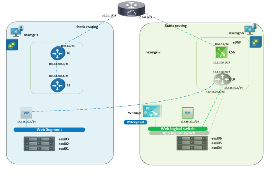
The below diagram is a high-level architecture of the process during the migration between NSX-V and NSX-T, we will cover in the premigration and post migration setup later in detail.

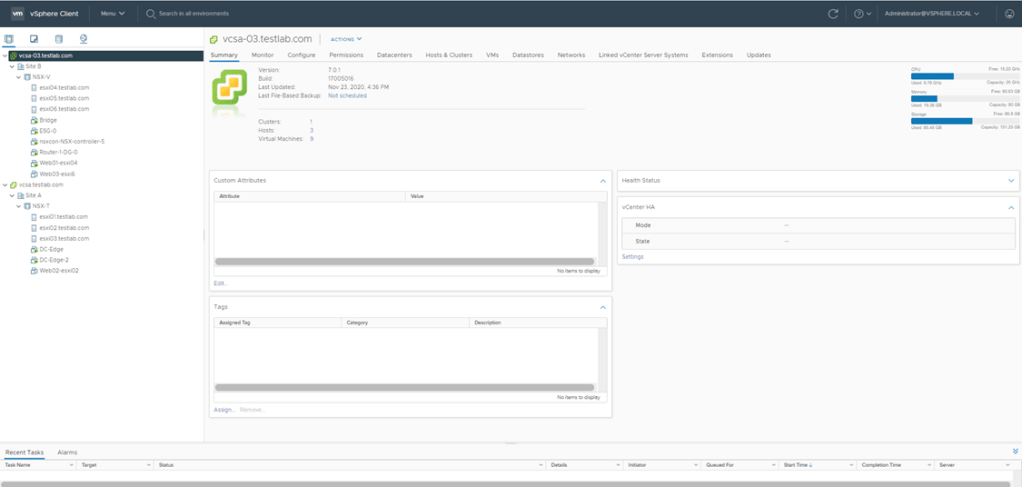
Home lab setup
In this set up I’m using the below:
- Physical hypervisor with the below specs:
- CPU:
- 2 CPUs (6 core) x Intel(R) Xeon(R) CPU E5-2640 0 @ 2.50GHz –>30GHZ
- Memory:
- 191.96 GB
- Storage:
- 1.08 TB
- CPU:
- 6 nested ESXi hosts (3 used for NSX-T and 3 used for NSX-V)
- The hosts are configured with 32 GB RAM each to prevent host preparation errors
- 2 vCenters with enhanced linked mode
- 2 NSX managers
- The first one is NSX-T manager
- The second one is NSX-V manager
- Cisco CSR 100 to act as the physical upstream router
NSX Managers setup
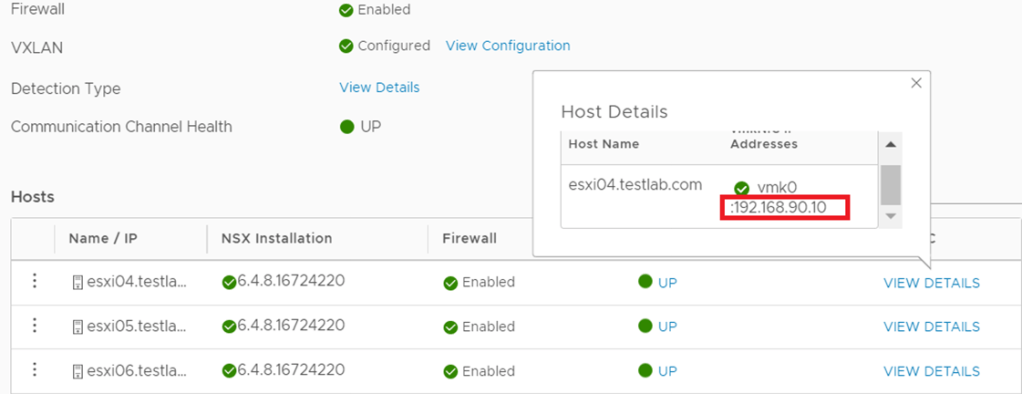
NSX-V: For the 3 hosts prepared for NSX-V, I used the IP Pool 192.168.90.0/24 subnet for host VTEPS as per the below:
NSX-T:
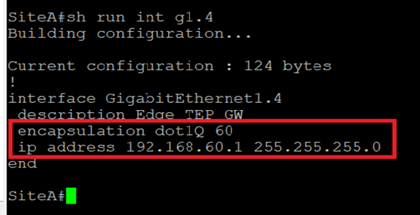
For the 3 hosts prepared for NSX-T, I used the IP pool 192.168.50.0/24 for the hosts TEPs and the IP pool 192.168.60.0/24 for the Edge TEPs (since edges are deployed on Prepared hosts):


To enable TEP communication between NSX-T hosts and Edges the below is configured on the Cisco CSR:
Host TEPs Default Gateway

TEPs Default Gateway
NSX-V:
In NSX-V environment I’ve created a 2 logical switches (App and Web), all the migration steps and bridging will be concerned with the Web subnet, the purpose of the App logical switch is to verify that a Web VM migrated to NSX-T can communicate with an App VM via bridging, the Web and App subnets are 172.16.20.0/24 and 172.16.30.0/24 respectively.
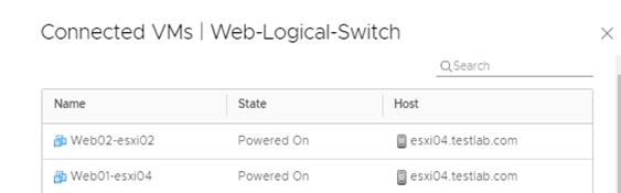
On the Web logical switch, there are 2 VMs (web01 and web02), this is the setup pre migration to NSX-T environment.

Both Logical switches have their default gateways on the DLR installed as per the below:

NSX-T: I created an overlay segment called Web, this is the segment where the migrated VMs from Web-logical switch will connect, bear in mind that during the migration, this segment is not connected to a Tier-1 gateway since all the egress traffic goes through the DLR interface if NSX-V.
Logical Routing
NSX-V
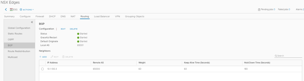
The logical routing configured here comprises of several parts, between DLR and ESG there is EBGP configured with a default route sent from ESG.
Between ESG and Cisco CSR (L3 device) static routing is configured.
DLR configuration

DLR Routing Table
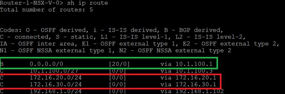
ESG Configuration
ESG Routing Table

Cisco CSR Routing configuration

NSX-T:
In this setup we have Tier 1 router which is still not connected to the web segment during the migration (it will be connected after the Default Gateway migration from NSX-V to NSX-T) A default route is configured between Tier 0 in NSX-T with the next hop the interface of the CSR. After migrating the Web VMs and their Default Gateway (connecting Web Segment to T1 and setting T1 interface to 172.16.20.1/24), we can then add on the CSR a more specific route “ ip route 172.16.20.0 255.255.255.0 10.0.1.2”, the reason behind this is for the CSR to be able to reach web VMs through Tier 0 and still reach App VMs ( not migrated to NSX-t) through ESG.
Tier 0 configuration

Tier 0 Routing Table

An important thing to note here before setting up any component in NSX-T, is that there was an abnormal behavior reported during the bridging scenario which was as follows, as you know all logical router interfaces have the MAC address “02:50:56:56:44:52”, which sometimes can cause a conflict between both environments (even though in NSX-T the Web segment is not connected to T1) yet this issue was reported on NSX-T 2.5. So, to avoid this we have 2 ways to change the MAC address of the router interfaces.
Either: Run the below to create an overlay transport zone with parameter “nested_nsx”: true which basically changes the MAC address of the router interfaces from “02:50:56:56:44:52” “02:50:56:56:44:53”

Or
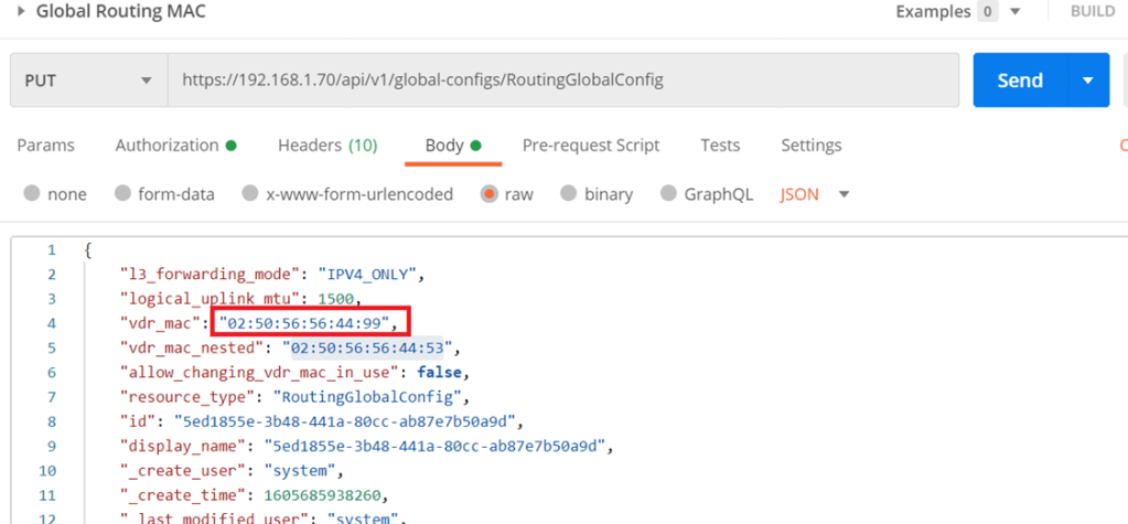
Starting NSX-T 3.0.2 you can change the MAC address of the logical interface through an API call (in case none of the transport nodes are created).
The difference here is that I set the MAC address to “02:50:56:56:44:99” which will take effect for any of the created T1 router interfaces
Moving forward, the concept of Edge bridge set up here is to be deployed on NSX-V cluster, which would give the edge bridge the visibility to logical switches configured in the NSX-V environment.
Normally in NSX-T when you deploy an edge VM, it’s uplinks are either connect to VLAN backed segment or DVS VLAN port groups, in this setup we are going to map the edge uplinks to DVS VLAN portgroups and NSX-V logical switche(s).
First of all, in the below edge configuration I’m bridging only one segment, which is the Web segment, however you can bridge another segment if required( App segment) by configuring only 1 uplink for the Overlay instead of 2, then add a 3rd NVDS in which its uplink is connected to the App logical switch (created in NSX-V)

- The Bridge-Trunk, is a trunk port group configured on the NSX-V VDS
- The Bridge TZ, is a VLAN TZ configured for bridging
- In The bridge NVDS, the fp-eth2 is mapped to the web logical switch configured in NSX-V
Which needs to be configured for promiscuous mode and forged transmits
The below screenshot is from the DVS configuration for clarity:


In the above I configured the edge bridge under the Web segment configured in NSX-T and you noticed VLAN 0 (NULL VLAN)
Bridging Validation and Migration
To verify the above setup is working correctly I did a cross vCenter VMotion for one web VM which was connected to the web logical switch to connect to the web segment configured in NSX-T environment.

We will do a couple of ping tests from web02 (172.16.20.3):
- ping 172.16.20.2 (web01)
- ping 172.16.20.1(DLR interface)
- ping 172.16.30.3(App 01)

So to deep dive in this part, when the web02 initiates a ping to 172.16.20.2(web-01 on NSX-V) for the first time, it will do an arp request which will be flooded depending on the logical switch replication mode (default is hierarchical but since all TEPS are in the same subnet so the BUM replication will be similar to head replication) so the host where web02 is deployed on will replicate the traffic and sends a copy to each TEP for that particular VNI (web segment), remember that the edge bridge is a transport node at the end and since it’s a member of the overlay transport zone where the web segment is deployed, it will receive the arp request decapsulates GENEVE and examines the request and since the edge bridge is deployed on an esxi host prepared for NSX-V then it will follow the logical switch replication for BUM traffic, the default is unicast, so the host will encapsulate the arp request using VXLAN to the rest of the hosts, finally the bridge MAC-address table will have web-01 MAC:

Edge Bridge MAC Address table

ESXi02 which hosts web02 MAC Address table
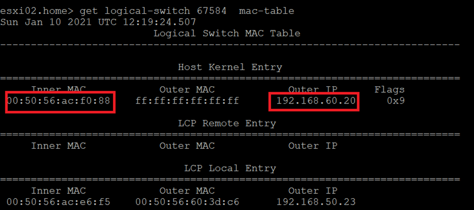
Notice here that the Outer IP address is the Edge bridge IP, so for future communication with Web01,
The ESXi02 host will encapsulate the traffic via GENEVE and the destination TEP will be the 192.168.60.20 which is the bridge TEP IP, the bridge then will decapsulate the GENEVE header and the ESXi host hosting the edge bridge will encapsulate the traffic via VLXLAN.
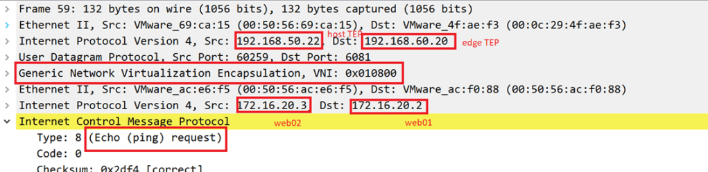
Let’s validate the above with packet captures( we will examine the ones having the destination IP 172.16.20.3 in detail, 172.16.20.1 and 172.16.30.3 should be similar)
Source IP: 172.16.20.3 (web02) on NSX-T segment Destination IP:172.16.20.2 (web01) on NSX-V logical segment
GENEVE Between ESXi02 (which hosts web02) and Edge Bridge
VXLAN between Edge Bridge and ESXi04(which hosts web01):

VXLAN between ESXi04 and ESXi hosting the Edge Bridge

GENEVE between Edge bridge and ESXi02

Gateway Migration
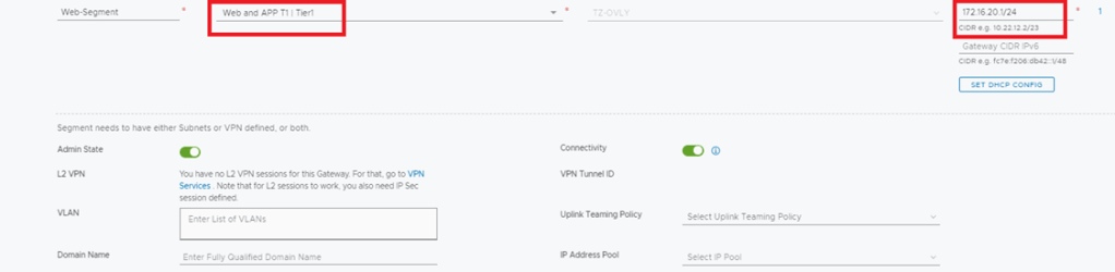
The final step is to migrate the gateway for the web segment to be the Tier 1 interface in NSX-T instead of the DLR interface in NSX-V
Let’s verify a couple of things:
Traceroute from CSR to web02(hosted on NSX-T segment)

Notice here the traffic from CSR to the web02 VM traverses the ESG and DLR routers like the below:
And the goal after the GW migration is to have the below final setup:
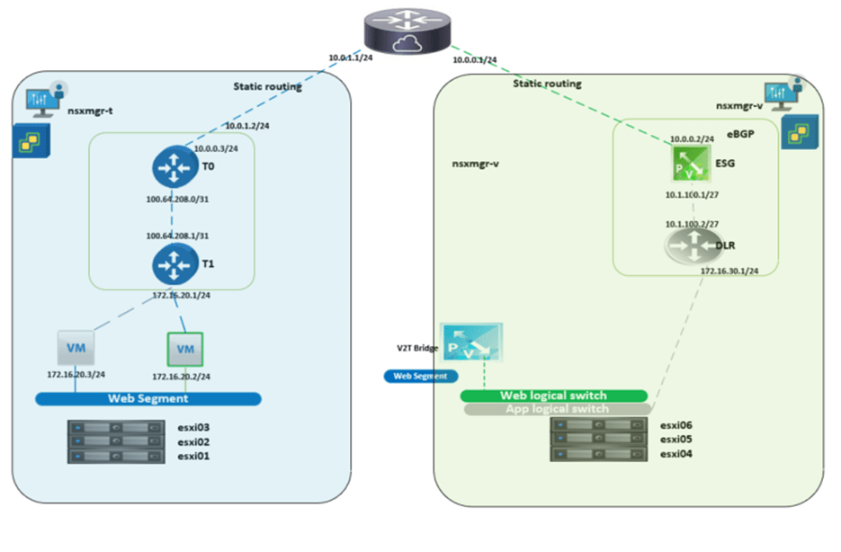
To achieve this final setup, we will configure the below:
-Disconnect DLR interface

-Add more specific route to the CSR for the web subnet (this is needed when there are still subnets communicating with web segment and still not migrated to NSX-T)

Let’s run the traceroute again from the CSR
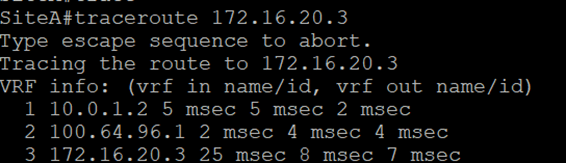
Now we notice the difference in trace before and after the GW migration.
The above completes the gateway migration simulation on a home lab, bear in mind that high availability was not taken into consideration, which should be noted in real life scenarios.
